Lexus IS250 IS220d GSE20 ALE20 - PARKING BRAKE
PARKING BRAKE PEDAL - INSTALLATION
| 1. INSTALL PARKING PEDAL PAD |

Engage the claw and install the parking pedal pad on the parking brake pedal.
| 2. INSTALL PARKING BRAKE PEDAL ASSEMBLY (for LHD) |

Pass the No. 1 parking brake cable assembly through the parking brake pedal and hold the cable with the clip.
- HINT:
- Fully tighten the No. 1 wire adjusting nut and lock nut when adjusting the parking brake pedal free play.
Fully bend the parking brake pedal claw.

Temporarily install the parking brake pedal by loosely tightening the 3 nuts.
Fully tighten the 3 nuts in the order shown in the illustration.
- Torque:
- 13 N*m{ 133 kgf*cm, 10 ft.*lbf}
Connect the parking brake switch connector.

Install the instrument panel junction block assembly with the 2 nuts.
Install the No. 1 parking brake cable assembly to the body with the 3 nuts and 2 bolts.
- Torque:
- Nut:
- 6.0 N*m{ 61 kgf*cm, 53 in.*lbf}
- Bolt:
- 8.0 N*m{ 82 kgf*cm, 71 in.*lbf}


Install the parking brake equalizer to the No. 1 parking brake cable assembly.

Slide the rubber boot back as shown in the illustration.

Connect the 2 No. 2 parking brake cable assemblies to the parking brake equalizer.
Install the 2 No. 2 prking brake cable assemblies with the 2 bolts.
- Torque:
- 6.0 N*m{ 61 kgf*cm, 53 in.*lbf}

Install the parking brake return with damper spring.
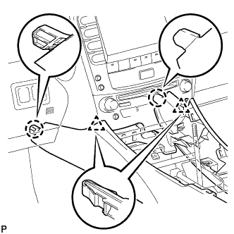
| 3. INSTALL PARKING BRAKE PEDAL ASSEMBLY (for RHD) |

Pass No. 1 parking brake cable assembly through the parking brake pedal and hold the cable with the clip.
- HINT:
- Fully tighten the No. 1 wire adjusting nut and lock nut when adjusting the parking brake pedal free play.
Fully bend the parking brake pedal claw.

Temporarily install the parking brake pedal by loosely tightening the 2 nuts and bolt.
Fully tighten the 2 nuts and bolt in the order shown in the illustration.
- Torque:
- Nut:
- 6.0 N*m{ 61 kgf*cm, 53 in.*lbf}
- Bolt:
- 8.0 N*m{ 82 kgf*cm, 71 in.*lbf}
Connect the parking brake switch connector.
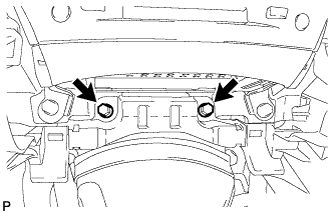
Install the instrument panel junction block assembly with the 2 nuts.
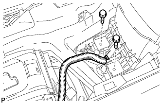
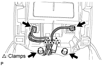
Install the No. 1 parking brake cable assembly to the body with the 3 nuts and 2 bolts.

Install the parking brake equalizer to the No. 1 parking brake cable assembly.
Slide the rubber boot back as shown in the illustration.
Connect the No. 2 parking brake cable assemblies to the parking brake equalizer.
Install the No. 2 parking brake cable assemblies with the 2 bolts.
- Torque:
- 6.0 N*m{ 61 kgf*cm, 53 in.*lbf}
Install the parking brake return with damper spring.
| 4. INSTALL AIR DUCT NO.1 (for RHD) |

Engage the claw and install the No. 1 air duct.
| 5. INSTALL FRONT UPPER FLOOR REAR SUB PANEL |

Install the front floor rear upper sub panel with the 4 bolts.
- Torque:
- 18 N*m{ 184 kgf*cm, 13 ft.*lbf}
Engage the 6 clamps.
| 6. INSTALL CENTER AIRBAG SENSOR ASSEMBLY |
Check that the engine switch is off.
Check that the battery negative (-) terminal is disconnected.
- NOTICE:
- After disconnecting the negative battery terminal, wait for at least 90 seconds before starting the operation.

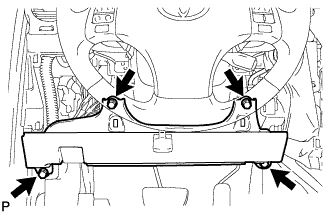
Install the center airbag sensor assembly with the nut and 2 bolts.
- Torque:
- 17.5 N*m{ 179 kgf*cm, 13 ft.*lbf}
- NOTICE:
Check that there is no looseness in the installation parts of the center airbag sensor assembly.
Connect the holder (with connectors).
Check that the water-proof sheet is properly set.
| 7. INSTALL NO. 3 DASH PANEL INSULATOR PAD |
Install the No. 3 dash panel insulator pad.
| 8. INSTALL PROPELLER SHAFT WITH CENTER BEARING ASSEMBLY |
- HINT:
- .
| 9. INSTALL NO. 2 REAR AIR DUCT |

Install the No. 2 console box duct with the 2 clips.
| 10. INSTALL FRONT FLOOR SILENCER PAD |
Install the front floor silencer pad.
| 11. INSTALL ACCELERATOR PEDAL |
- HINT:
- .
| 12. INSTALL DRIVER SIDE KNEE AIRBAG ASSEMBLY |
Connect the connector.
- NOTICE:
- When handling the airbag connector, take care not to damage the airbag wire harness.
Install the driver side knee airbag assembly with the 4 bolts.
- Torque:
- 10 N*m{ 102 kgf*cm, 7 ft.*lbf}
| 13. INSTALL LOWER INSTRUMENT FINISH PANEL SUB-ASSEMBLY |
Connect the connectors.
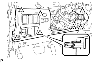
Engage the 7 clips and install the lower instrument panel finish panel sub-assembly.
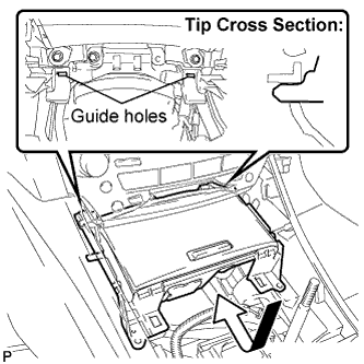
| 14. INSTALL NO. 1 INSTRUMENT PANEL UNDER COVER SUB-ASSEMBLY |
Connect the connectors.
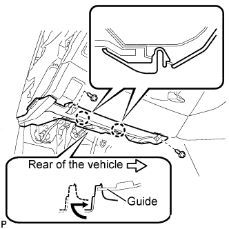
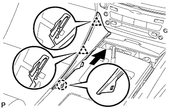
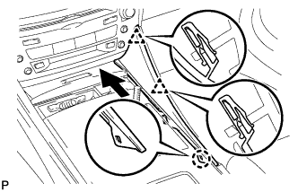
Insert the No. 1 instrument panel under cover sub-assembly into the guide as shown in the illustration.
Engage the 2 claws.
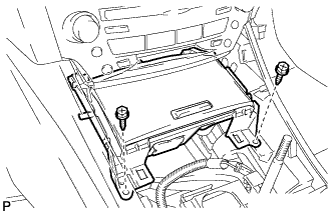
Install the No. 1 instrument panel under cover sub-assembly with the 2 screws <E-.
| 15. INSTALL SIDE INSTRUMENT PANEL LH |
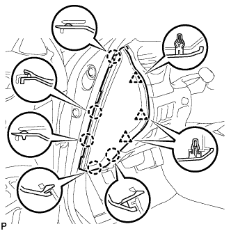
Engage the 5 claws and 3 clips, and then install the side instrument panel LH.
| 16. INSTALL CONSOLE BOX |
Engage the 2 claws and 2 clips.
Install the 2 bolts <C-.
Install the 2 bolts <C-.
Connect the connector.
Connect the connectors.
Engage the 2 clamps.
Install the 2 bolts <C-.
| 17. INSTALL CONSOLE BOX REGISTER ASSEMBLY |
Engage the 2 claws and 4 clips, and then install the console box register assembly.
Install the rear ash receptacle assembly.
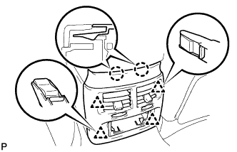
| 18. INSTALL FRONT ASH RECEPTACLE ASSEMBLY |
Connect the connectors.
Insert the protruding parts of the front ash receptacle sub-assembly into the 2 guide holes as shown in the illustration.
Install the front ash receptacle sub-assembly with the 2 screws <F-.
| 19. INSTALL CONSOLE PANEL SUB-ASSEMBLY |
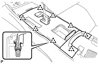
Connect the connectors.
Engage the 8 clips and install the console panel sub-assembly.
| 20. INSTALL NO. 1 UPPER CONSOLE PANEL GARNISH |
Engage the claw and 2 clips, and then install the upper No. 1 console panel garnish.
| 21. INSTALL NO. 2 UPPER CONSOLE PANEL GARNISH |
Engage the claw and 2 clips, and then install the upper No. 2 console panel garnish.
| 22. INSTALL SHIFT LEVER KNOB SUB-ASSEMBLY |

Turn the shift knob clockwise and install the shift lever knob sub-assembly.
| 23. INSTALL CENTER LOWER PILLAR GARNISH LH |

Engage the 5 clips and 3 claws, and install the lower center pillar garnish LH.
| 24. INSTALL REAR DOOR SCUFF PLATE LH |

Engage the 2 clips.

Engage the 5 claws and install the rear door scuff plate LH.
| 25. INSTALL FRONT DOOR SCUFF PLATE LH (w/o Illumination) |

Engage the 4 clips.

Engage the 7 claws, and install the front door scuff plate LH.
| 26. INSTALL FRONT DOOR SCUFF PLATE LH (w/ Illumination) |
Connect the connector.
Engage the 4 clips.
Engage the 7 claws, and install the front door scuff plate LH.
| 27. INSTALL FRONT DOOR OPENING TRIM COVER LH |

Engage the 4 claws and install the front door opening trim cover LH.
| 28. INSTALL FRONT SEAT OUTER BELT ASSEMBLY |
- HINT:
- .
| 29. INSTALL REAR SEAT CUSHION ASSEMBLY |
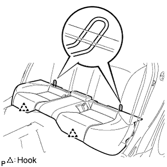
Attach the 2 rear hooks of the seat cushion to the seatback.
Attach the 2 front hooks of the seat cushion to the vehicle body.
Confirm that the seat cushion is firmly installed.
- NOTICE:
- When installing the seat cushion, make sure the seat belt buckle is not under the seat cushion.
| 30. INSTALL FRONT SEAT ASSEMBLY (for Power Seat) |
- HINT:
- .
| 31. INSTALL FRONT SEAT ASSEMBLY (for Manual Seat) |
- HINT:
- .
| 32. CONNECT CABLE TO NEGATIVE BATTERY TERMINAL |
- Torque:
- 5.4 N*m{ 55 kgf*cm, 48 in.*lbf}
| 33. INSPECT PARKING BRAKE PEDAL TRAVEL |
Fully depress the parking brake pedal and release it to engage the parking brake.
Depress the pedal to the floor again, and release it to disengage the parking brake.

Slowly depress the parking brake pedal to the floor, and count the number of clicks.
- Parking brake pedal travel:
- 7 to 9 notches at 300 N (31 kgf, 67.5 lbf)
| 34. ADJUST PARKING BRAKE PEDAL TRAVEL |
Depress the parking brake pedal. Hold the No. 1 wire adjusting nut using a wrench and loosen the lock nut.
Release the parking brake pedal.

Turn the No. 1 wire adjusting nut until the parking brake pedal travel meets the above specification.
Hold the wire adjusting No. 1 nut using a wrench or equivalent tool and tighten the lock nut.
- Torque:
- 6.0 N*m{ 61 kgf*cm, 53 in.*lbf}
Count the number of clicks after depressing and releasing the parking brake pedal 3 or 4 times.
Check whether the parking brake drags or not.
When operating the parking brake pedal, check that the parking brake indicator light comes on.
| 35. PERFORM INITIALIZATION |
- HINT:
| 36. INSPECT SRS WARNING LIGHT |
- HINT:
- .
| 37. INSPECT FRONT SEAT ASSEMBLY (for Power Seat) |
Check the power seat operation.
Check the seat heater operation (with seat heater system).
Turn the engine switch on (IG).
Turn the seat heater switch ON.
Wait 5 minutes or more and confirm that the seat surface becomes warm.
| 38. CHECK FOR EXHAUST GAS LEAKS |