Lexus IS250 IS220d GSE20 ALE20 4GR-FSE STARTING
ENTRY AND START SYSTEM - TERMINALS OF ECU
| CHECK POWER SOURCE CONTROL ECU |

Disconnect the J55 ECU connector.
Measure the voltage and resistance of the wire harness side connector.
| Symbols (Terminal No.) | Wiring Color | Terminal Description | Condition | Specified Condition |
| AM1 (J55-33) - Body ground | O - Body ground | +B power supply | Always | 10 to 14 V |
| AM2 (J55-12) - Body ground | O - Body ground | +B power supply | Always | 10 to 14 V |
| SSW1 (J55-14) - Body ground | B - Body ground | Engine switch signal | Engine switch pushed | Below 1 Ω |
| SSW1 (J55-14) - Body ground | B - Body ground | Engine switch signal | Engine switch not pushed | 10 kΩ or higher |
| SSW2 (J55-37) - Body ground | SB - Body ground | Engine switch signal | Engine switch pushed | Below 1 Ω |
| SSW2 (J55-37) - Body ground | SB - Body ground | Engine switch signal | Engine switch not pushed | 10 kΩ or higher |
| GND2 (J55-6) - Body ground | W-B - Body ground | Ground | Always | Below 1 Ω |
| LIN1 (J55-30) - Body ground | V - Body ground | LIN line | Always | 10 kΩ or higher |
| MPX1 (J55-7) - Body ground | GR - Body ground | MPX line | Always | 10 kΩ or higher |
| MPX2 (J55-24) - Body ground | GR - Body ground | MPX line | Always | 10 kΩ or higher |
If the result is not as specified, there may be a malfunction on the wire harness side.
Reconnect the J55 ECU connector.
Measure the voltage of the connector.
| Symbols (Terminal No.) | Wiring Color | Terminal Description | Condition | Specified Condition |
| ACCD (J55-11) - GND2 (J55-6) | LG - W-B | ACC signal | Engine switch on (ACC) | Output voltage at terminal AM2 is -2 V or more. |
| ACCD (J55-11) - GND2 (J55-6) | LG - W-B | ACC signal | Engine switch off | Below 1 V |
| IG1D (J55-34) - GND2 (J55-6) | P - W-B | IG1 signal | Engine switch on (IG) | Output voltage at terminal AM2 is -2 V or more. |
| IG1D (J55-34) - GND2 (J55-6) | P - W-B | IG1 signal | Engine switch on (ACC) | Below 1 V |
| IG2D (J55-35) - GND2 (J55-6) | LG - W-B | IG2 signal | Engine switch on (IG) | Output voltage at terminal AM2 is -2 V or more. |
| IG2D (J55-35) - GND2 (J55-6) | LG - W-B | IG2 signal | Engine switch on (ACC) | Below 1 V |
| STP (J55-1) - GND2 (J55-6) | R - W-B | Stop light signal | Brake pedal depressed | Output voltage at terminal AM2 is -2 V or more. |
| STP (J55-1) - GND2 (J55-6) | R - W-B | Stop light signal | Brake pedal released | Below 1 V |
| SLR+ (J55-32) - GND2 (J55-6) | W - W-B | Steering lock motor signal | Steering lock motor operating | Below 1 V |
| SLR+ (J55-32) - GND2 (J55-6) | W - W-B | Steering lock motor signal | Steering lock motor does not operate | Output voltage at terminal AM2 is -2 V or more. |
| SLP (J55-26) - GND2 (J55-6) | R - W-B | Steering lock actuator position signal | Steering lock is locked | Pulse generation (See waveform 3) |
| SLP (J55-26) - GND2 (J55-6) | R - W-B | Steering lock actuator position signal | Steering lock is released | Pulse generation (See waveform 3) |
| SPD (J55-19) - GND2 (J55-6) | P - W-B | Vehicle speed signal | Engine switch on (IG), rotate rear wheel slowly | Pulse generation (See waveform 1) |
| TACH (J55-2) - GND2 (J55-6) | W - W-B | Tachometer signal | Engine running | Pulse generation (See waveform 2) |
| P (J55-5) - GND2 (J55-6) *3 | BR - W-B | Shift lock signal | Shift lever P position | Output voltage at terminal AM2 is -2 V or more. |
| P (J55-5) - GND2 (J55-6) *3 | BR - W-B | Shift lock signal | Shift lever not P position | Below 1 V |
| CTSW (J55-31) - GND2 (J55-6) | LG - W-B | Starter assist signal | Brake pedal depressed, shift lever P position, engine switch is pushed once → on (IG) | 0.1 to 0.8 V *1
→ Output voltage at terminal AM2 is -2 V or more. |
| STSW (J55-39) - GND2 (J55-6) | L - W-B | Starter activation request signal | Brake pedal (A/T) or clutch pedal (M/T) depressed, engine switch hold on (ST) | Output voltage at terminal AM2 is -2 V or more. |
| STR1 (J55-17) - GND2 (J55-6) | SB - W-B | Park / neutral position switch *3
Clutch start switch *4 | Shift lever P or N (A/T) position Clutch pedal depressed (M/T) | Below 1 V |
| STR2 (J55-15) - GND2 (J55-6) | V - W-B | Starter signal | Brake pedal (A/T) or clutch pedal (M/T) depressed, shift lever P or N position (A/T), engine switch on (ST) | Output voltage at terminal AM2 is -2 V or more. *2 |
| INDS (J55-4) - GND2 (J55-6) | L - W-B | Vehicle condition signal | Brake pedal (A/T) or clutch pedal (M/T) depressed, shift lever P position (A/T). | Output voltage at terminal AM2 is -2 V or more. |
| INDW (J55-13) - GND2 (J55-6) | BR - W-B | Warning signal | Brake pedal (A/T) or clutch pedal (M/T) depressed, shift lever P position (A/T), engine switch on (ACC, IG) | Output voltage at terminal AM2 is -2 V or more. |
| SWIL (J55-36) - GND2 (J55-6) | Y - W-B | Illumination signal | Light control switch TAIL or HEAD | Output voltage at terminal AM2 is -2 V or more. |
| SKSW (J55-28) - GND2 (J55-6) | B - W-B | Key in vehicle signal | Engine switch on (ACC, IG) | Below 1 V |
- HINT:
- *1: Voltage is output only when the engine is cranking.
- *2: Voltage is output for 0.3 seconds when engine is cranking start. Disconnect the E4 connector from the ECM before measuring the voltage.
- *3: A/T
- *4: M/T
If the result is not as specified, the ECU may have a malfunction.
Using an oscilloscope, check the signal waveform of the ECU.
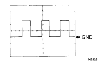
Waveform 1
| Terminal No. | J55-19 - Body ground |
| Tool Setting | 5 V/DIV., 10 ms./DIV. |
| Vehicle Condition | Driving at approx. 20 km/h (12 mph) |
- HINT:
- As the vehicle speed increases, the wavelength shortens.
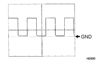
Waveform 2
| Terminal No. | J55-2 - Body ground |
| Tool Setting | 5 V/DIV., 10 ms./DIV. |
| Vehicle Condition | Engine idling |
- HINT:
- As the engine revolution speed increases, the wavelength shortens.
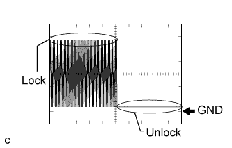
Waveform 3
| Terminal No. | J55-26 - Body ground |
| Tool Setting | 2 V/DIV., 100 ms./DIV. |
| Vehicle Condition | Steering lock / unlock |
| CHECK CERTIFICATION ECU |

Disconnect the P33 ECU connector.
Measure the voltage and resistance of the wire harness side connector.
| Symbols (Terminal No.) | Wiring Color | Terminal Description | Condition | Specified Condition |
| +B1 (P33-1) - Body ground | L - Body ground | +B power supply | Always | 10 to 14 V |
| IG (P33-18) - Body ground | B - Body ground | Ignition power supply | Engine switch on (IG) | 10 to 14 V |
| IG (P33-18) - Body ground | B - Body ground | Ignition power supply | Engine switch off | Below 1 V |
| LIN (P33-10) - Body ground | V - Body ground | LIN line | Always | 10 kΩ or higher |
| E (P33-17) - Body ground | W-B - Body ground | Ground | Always | Below 1 Ω |
If the result is not as specified, there may be a malfunction on the wire harness side.
| CHECK ECM |
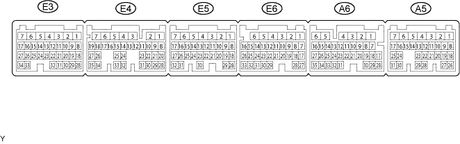
Disconnect the A5, E5, E4, E3 and E6 ECM connectors.
Measure the voltage and resistance of the wire harness side connectors.
| Symbols (Terminal No.) | Wiring Color | Terminal Description | Condition | Specified Condition |
| +B (A5-6) - Body ground | B-R - Body ground | Power source of ECM | Engine switch on (IG) | 10 to 14 V |
| +B1 (A5-5) - Body ground | B-R - Body ground | Power source of ECM | Engine switch on (IG) | 10 to 14 V |
| IGSW (A5-17) - Body ground | B-W - Body ground | Ignition switch signal | Engine switch on (IG) | 10 to 14 V |
| E01 (E5-2) - Body ground | W-B - Body ground | Ground | Always | Below 1 Ω |
| E02 (E5-1) - Body ground | W-B - Body ground | Ground | Always | Below 1 Ω |
| E03 (E3-6) - Body ground | W-B - Body ground | Ground | Always | Below 1 Ω |
| E04 (E6-5) - Body ground | W-B - Body ground | Ground | Always | Below 1 Ω |
| E05 (E6-3) - Body ground | W-B - Body ground | Ground | Always | Below 1 Ω |
| E1 (E4-7) - Body ground | BR - Body ground | Ground | Always | Below 1 Ω |
| EC (A5-2) - Body ground | W-B - Body ground | Ground | Always | Below 1 Ω |
| ME01 (E3-4) - Body ground | W-B - Body ground | Ground | Always | Below 1 Ω |
If the result is not as specified, there may be a malfunction on the wire harness side.
Reconnect the A5, E5, E4, E3 and E6 ECM connectors.
Measure the voltage of the connectors.
| Symbols (Terminal No.) | Wiring Color | Terminal Description | Condition | Specified Condition |
| STA (A5-12) - E1 (E4-7) | R - BR | Starter relay operation signal | Cranking | 10 to 14 V |
| ACCR (A5-11) - E1 (E4-7) | W-L - BR | ACC relay cut signal (output) | Engine switch on (IG) | 10 to 14 V |
| TACH (A6-16) - E1 (E4-7) | R-W - BR | Engine revolution signal (output) | Idling | Pulse generation (see waveform 1) |
| STP (A6-4) - E1 (E4-7) | R-B - BR | Stop light switch signal (input) | Brake pedal depressed | 7.5 to 14 V |
| STP (A6-4) - E1 (E4-7) | R-B - BR | Stop light switch signal (input) | Brake pedal released | Below 1.5 V |
| STAR (E4-4) - E1 (E4-7) | L-Y - BR | PNP switch signal (input) | Engine switch on (IG), shift position P or N | 10 to 14 V |
| KSW (A5-23) - E1 (E4-7) | L-R - BR | Engine switch signal (input) | Engine switch off | 4 to 6 V |
| KSW (A5-23) - E1 (E4-7) | L-R - BR | Engine switch signal (input) | When engine switch is pushed once | 10 to 14 V |
| KSW (A5-23) - E1 (E4-7) | L-R - BR | Engine switch signal (input) | Engine switch on (ACC) | Below 1.5 V |
If the result is not as specified, the ECM may have a malfunction.
Using an oscilloscope, check the signal waveform of the ECM.
| Terminal No. | A6-16 - E7-4 |
| Tool Setting | 5 V/DIV., 10 ms./DIV. |
| Vehicle Condition | Engine idling |
- HINT:
- As the vehicle speed increases, the wavelength shortens.
| CHECK STEERING LOCK ECU |
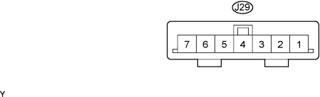
Disconnect the J29 ECU connector.
Measure the voltage and resistance of the wire harness side connector.
| Symbols (Terminal No.) | Wiring Color | Terminal Description | Condition | Specified Condition |
| B (J29-7) - Body ground | O - Body ground | +B power supply | Always | 10 to 14 V |
| IG2 (J29-6) - Body ground | LG - Body ground | Ignition power supply | Engine switch on (IG) | 10 to 14 V |
| IG2 (J29-6) - Body ground | LG - Body ground | Ignition power supply | Engine switch off | Below 1 V |
| GND (J29-1) - Body ground | W-B - Body ground | Ground | Always | Below 1 Ω |
| SGND (J29-2) - Body ground | W-B - Body ground | Ground | Always | Below 1 Ω |
Reconnect the J29 ECU connector.
Measure the voltage of the connector.
| Symbols (Terminal No.) | Wiring Color | Terminal Description | Condition | Specified Condition |
| SLP1 (J29-4) - GND (J29-1) | R - W-B | Steering lock actuator position signal | Steering is locked | 10 to 14 V |
| SLP1 (J29-4) - GND (J29-1) | R - W-B | Steering lock actuator position signal | Steering is released | Below 1 V |