Lexus IS250 IS220d GSE20 ALE20 4GR-FSE FUEL
FUEL TANK - INSTALLATION
| 1. INSTALL NO. 2 FUEL TANK PROTECTOR |
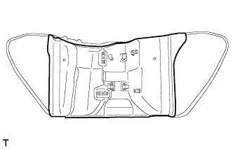
Install the No. 2 fuel tank protector to the fuel tank assembly.
| 2. INSTALL FUEL TANK CUSHION |
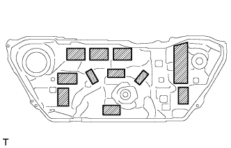
Install 11 new fuel tank cushions as shown in the illustration.
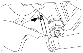
| 3. INSTALL FUEL TANK VENT HOSE |
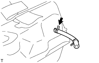
Install the fuel tank vent hose with the clip.
| 4. INSTALL FUEL TANK TO FILLER PIPE HOSE |
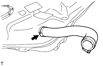
Install the fuel tank to filler pipe hose to the fuel tank with the clamp.
Tighten the hose clamp bolt.
| 5. INSTALL FUEL TUBE SUB-ASSEMBLY |
Install the edge protector with the 2 clamps.
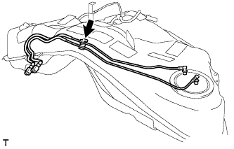
Install a fuel tank main tube and fuel tank return vent tube with the clamp.
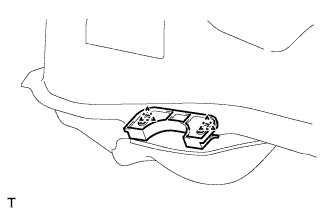
| 6. INSTALL NO. 1 FUEL TANK BREATHER TUBE SUB-ASSEMBLY |
Install a new gasket to the No. 1 fuel tank breather tube sub-assembly.
Install the No. 1 fuel tank breather tube sub-assembly with the 4 bolts.
- Torque:
- 1.5 N*m{ 15 kgf*cm, 13 in.*lbf}
| 7. INSTALL FUEL TANK ASSEMBLY |
Set the fuel tank assembly onto the transmission jack.
Raise the transmission jack so that the fuel tank breather hose can be connected. Connect the hose.
- NOTICE:
- Slowly raise the jack not to drop the fuel tank assembly.
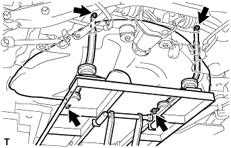
Install the fuel tank assembly with the fuel tank band and 4 bolts.
- Torque:
- 39 N*m{ 400 kgf*cm, 29 ft.*lbf}
| 8. CONNECT FUEL TANK VENT HOSE |
Connect the fuel tank vent hose with the clamp.
| 9. CONNECT FUEL TANK TO FILLER PIPE HOSE |
Connect the fuel tank to filler pipe hose with the clamp.
| 10. CONNECT FUEL TUBE SUB-ASSEMBLY |
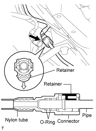
Connect the fuel tank main tube.
Push in the fuel tube connector to the pipe and push up the retainer to engage the claws.
- NOTICE:
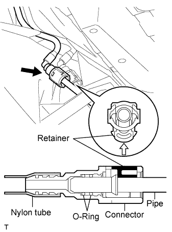
Connect the fuel tank return vent tube.
Push in the fuel tube connector to the pipe and push up the retainer to engage the claws.
- NOTICE:
| 11. CONNECT PARKING BRAKE CABLE ASSEMBLY |
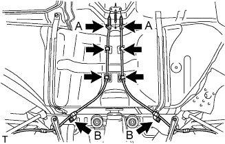
Connect the 4 clamps.
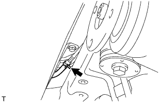
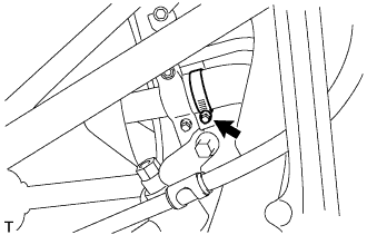
Connect the 2 parking brake cables with the 4 bolts.
- Torque:
- 6.0 N*m{ 61 kgf*cm, 53 in.*lbf}for bolt A
- 19 N*m{ 194 kgf*cm, 14 ft.*lbf}for bolt B
| 12. INSTALL REAR SUSPENSION MEMBER BRACE LH |
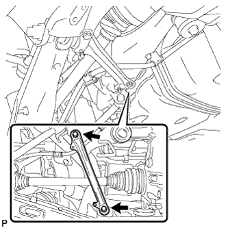
Install the rear suspension member brace LH with the 2 bolts.
- Torque:
- 50 N*m{ 510 kgf*cm, 37 ft.*lbf}
| 13. INSTALL REAR SUSPENSION MEMBER BRACE RH |
- HINT:
- Installation procedure of the RH side is the same as that of the LH side.
| 14. INSTALL NO. 1 FLOOR UNDER COVER |
| 15. INSTALL NO. 2 FLOOR UNDER COVER |
| 16. INSTALL NO. 2 DIFFERENTIAL SUPPORT PROTECTOR |
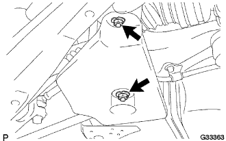
Install the No. 2 differential support protector to the rear suspension member brace with the 2 nuts.
- Torque:
- 5.4 N*m{ 55 kgf*cm, 48 in.*lbf}
| 17. INSTALL NO. 1 DIFFERENTIAL SUPPORT PROTECTOR |
- HINT:
- Installation procedure of the No. 1differential support protector is the same as that of the No. 2 differential support protector.
| 18. INSTALL PROPELLER SHAFT WITH CENTER BEARING ASSEMBLY |
- HINT:
- .
| 19. INSTALL FRONT EXHAUST PIPE ASSEMBLY |
- HINT:
- .
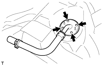
| 20. INSTALL FUEL SENDER GAUGE ASSEMBLY |
Install the fuel sender gauge to the fuel tank with the 5 bolts.
- Torque:
- 1.5 N*m{ 15 kgf*cm, 13 in.*lbf}
Connect the fuel sender gauge connector.
| 21. INSTALL FUEL SUCTION WITH PUMP AND GAUGE TUBE ASSEMBLY |
Install a new gasket onto the fuel tank.
Connect the fuel hose with the clip.
Set the fuel suction tube to the fuel tank.
- NOTICE:
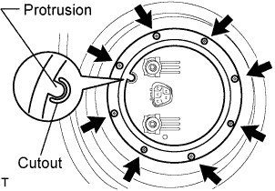
Align the protrusion of the fuel suction tube and the cutout of the fuel tank vent tube set plate.
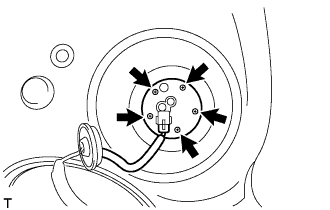
While holding the fuel suction tube by hand, install the fuel tank vent tube to the fuel tank with the 8 bolts.
- Torque:
- 6.0 N*m{ 61 kgf*cm, 53 in.*lbf}
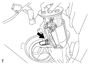
Connect the fuel tube.
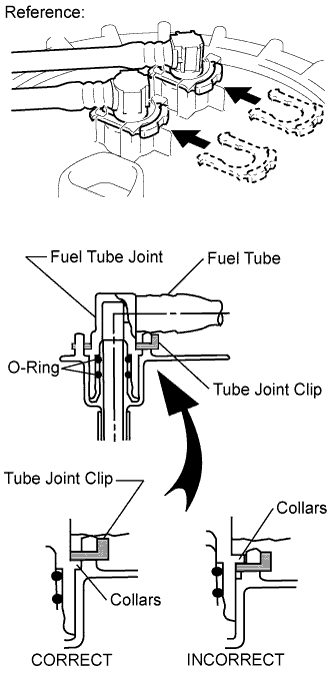
Push the fuel tube joint in the plug of the fuel suction plate, then install the 2 tube joint clips.
- NOTICE:
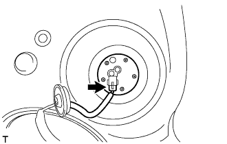
Connect the fuel suction tube connector.
| 22. ADD FUEL |
| 23. CONNECT CABLE TO NEGATIVE BATTERY TERMINAL |
- Torque:
- 5.4 N*m{ 55 kgf*cm, 48 in.*lbf}
| 24. CHECK FOR FUEL LEAKAGE |
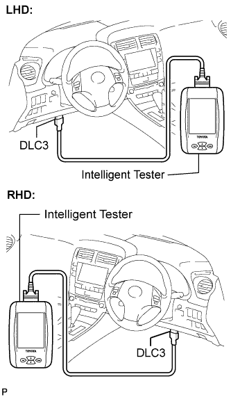
Connect the intelligent tester to the DLC3.
Turn the engine switch on (IG).
- NOTICE:
- Do not start the engine.
Push the intelligent tester main switch ON.
Select the following menus: Powertrain / Engine / Active Test / Control the Fuel Pump /Speed.
Check the fuel pump operation.
Check for pressure in the fuel inlet tube from the fuel line. Check that sound of fuel flowing in the fuel tank can be heard.
If no sound can be heard, check the integration relay, fuel pump, ECM and wiring connector.
Check for fuel leaks.
Check that there are no fuel leaks anywhere on the system after performing maintenance.
If there is a fuel leak, repair or replace parts as necessary.
| 25. CHECK FOR EXHAUST GAS LEAKAGE |
| 26. INSTALL REAR FLOOR SERVICE HOLE COVER |
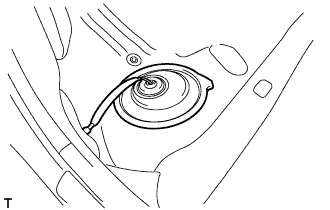
Install the service hole cover with new butyl tape.
| 27. INSTALL NO.2 REAR FLOOR SERVICE HOLE COVER |
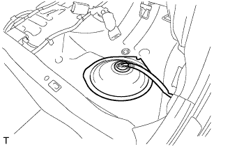
Install the No. 2 rear floor service hole cover with new butyl tape.
| 28. INSTALL REAR SEAT CUSHION ASSEMBLY |
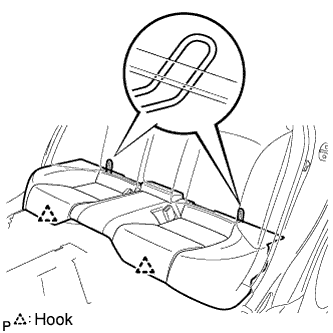
Attach the 2 rear hooks of the seat cushion to the seatback.
Attach the 2 front hooks of the seat cushion to the vehicle body.
Confirm that the seat cushion is firmly installed.
- NOTICE:
- When installing the seat cushion, make sure the seat belt buckle is not under the seat cushion.
| 29. PERFORM INITIALIZATION |
Perform initialization .
- HINT:
- Certain systems need to be initialized after reconnecting the cable to the negative (-) battery terminal.