Lexus IS250 IS220d GSE20 ALE20 4GR-FSE ENGINE CONTROL SYSTEM
SFI SYSTEM - FREEZE FRAME DATA
| DESCRIPTION |
Freeze frame data records the engine conditions (fuel system, calculated load, engine coolant temperature, fuel trim, engine speed, vehicle speed, etc.) when a malfunction is detected. When troubleshooting, freeze frame data can help determine if the vehicle was running or stopped, if the engine was warmed up or not, if the air-fuel ratio was Lean or Rich, and other data from the time the malfunction occurred.
- HINT:
- If it is impossible to replicate the problem even though a DTC is detected, confirm the freeze frame data.
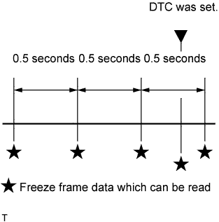
3 data set before the DTC was set.
1 data set when the DTC was set.
1 data set after the DTC was set.
These data sets can be used to simulate the condition of the vehicle around the time of the occurrence of the malfunction. The data may assist in identifying of the cause of the malfunction, and in judging whether it was temporary or not.
| LIST OF FREEZE FRAME DATA |
| LABEL (Intelligent Tester Display) | Measure Item/Range | Diagnostic Note |
| Trouble Code | Freeze DTC | - |
| Injector | Injector | - |
| IGN Advance | Ignition advance | - |
| Calculate load | Calculate load | Calculated load by ECM |
| Vehicle Load | Vehicle load | - |
| MAF | Mass air flow volume | If value approximately 0.0 g/s: Mass air flow meter power source circuit open or short VG circuit open or short E2G circuit open |
| Engine Speed | Engine speed | - |
| Vehicle Speed | Vehicle speed | Speed indicated on speedometer |
| Coolant Temp | Engine coolant temperature | If value -40°C, sensor circuit open If value 140°C, sensor circuit shorted |
| Intake Air | Intake air temperature | If value -40°C, sensor circuit open If value 140°C, sensor circuit shorted |
| Fuel Press | Fuel Pressure | - |
| Air-Fuel Ratio | Air-fuel ratio | - |
| Ambient Temperature | Ambient temperature | - |
| Purge Density Learn Value | Learning value of purge density | - |
| Purge Flow | Purge flow | - |
| EVAP (Purge) VSV | EVAP purge VSV duty ratio | - |
| Knock Correct Learn Value | Correction learning value of knocking | - |
| Knock Feedback Value | Feedback value of knocking | - |
| Accelerator Position No. 1 | Absolute Accelerator Pedal Position (APP) No. 1 | - |
| Accelerator Position No. 2 | Absolute APP No. 2 | - |
| Throttle Position | Throttle position | Read value with engine switch on (IG) (Do not start engine) |
| Throttle Sensor Position | Throttle sensor positioning | Read value with engine switch on (IG) (Do not start engine) |
| Throttle Sensor Position #2 | Throttle sensor positioning #2 | - |
| Throttle Motor | Throttle actuator | - |
| O2S B1 S2 | Heated oxygen sensor output | Performing Control the Injection Volume or Control the Injection Volume for A/F Sensor function of Active Test enables technician to check output voltage of sensor |
| O2S B2 S2 | Heated oxygen sensor output | Performing Control the Injection Volume or Control the Injection Volume for A/F Sensor function of Active Test enables technician to check output voltage of sensor |
| AFS B1 S1 | A/F sensor output | Performing Control the Injection Volume or Control the Injection Volume for A/F Sensor function of Active Test enables technician to check output voltage of sensor |
| AFS B2 S1 | A/F sensor output | Performing Control the Injection Volume or Control the Injection Volume for A/F Sensor function of Active Test enables technician to check output voltage of sensor |
| Total FT #1 | Total fuel trim | - |
| Total FT #2 | Total fuel trim | - |
| Short FT #1 | Short-term fuel trim | Short-term fuel compensation used to maintain air-fuel ratio at stoichiometric air-fuel ratio |
| Long FT #1 | Long-term fuel trim | Overall fuel compensation carried out in long-term to compensate a continual deviation of short-term fuel trim from central valve |
| Short FT #2 | Short-term fuel trim | Short-term fuel compensation used to maintain air-fuel ratio at stoichiometric air-fuel ratio |
| Long FT #2 | Long-term fuel trim | Overall fuel compensation carried out in long-term to compensate a continual deviation of short-term fuel trim from central valve |
| Fuel System Status (Bank 1) | Fuel system status (Bank 1) | OL (Open Loop): Has not yet satisfied conditions to go closed loop CL (Closed Loop): Using heated oxygen sensor as feedback for fuel control OL DRIVE: Open loop due to driving conditions (fuel enrichment) OL FAULT: Open loop due to detected system fault CL FAULT: Closed loop but heated oxygen sensor, which used for fuel control malfunctioning |
| Fuel System Status (Bank 2) | Fuel system status (Bank 2) | OL (Open Loop): Has not yet satisfied conditions to go closed loop CL (Closed Loop): Using heated oxygen sensor as feedback for fuel control OL DRIVE: Open loop due to driving conditions (fuel enrichment) OL FAULT: Open loop due to detected system fault CL FAULT: Closed loop but heated oxygen sensor, which used for fuel control malfunctioning |
| O2FT B1 S2 | Fuel trim at heated oxygen sensor | Same as Short FT #1 |
| O2FT B2 S2 | Fuel trim at heated oxygen sensor | Same as Short FT #1 |
| AF FT B1 S1 | Fuel trim at A/F sensor | - |
| AF FT B2 S1 | Fuel trim at A/F sensor | - |
| Catalyst Temp (B1 S1) | Catalyst temperature | - |
| Catalyst Temp (B1 S2) | Catalyst temperature | - |
| Catalyst Temp (B2 S1) | Catalyst temperature | - |
| Catalyst Temp (B2 S2) | Catalyst temperature | - |
| Initial Engine Coolant Temp | Initial engine coolant temperature | - |
| Initial Intake Air Temp | Initial intake air temperature | - |
| Injection Volume (Cylinder 1) | Injection volume | - |
| Injection Timing (D4) | Injection timing (D4) | - |
| SCV Status (D4) | SCV status (D4) | - |
| SCV Angle (D4) | SCV angle (D4) | - |
| SCV Angle Sensor (D4) | SCV angle sensor (D4) | - |
| Fuel Pump Duty (D4) | Fuel pump duty (D4) | - |
| Combustion Status (D4) | Combustion status (D4) | - |
| ACC Relay | ACC relay | - |
| Starter Relay | Starter relay | - |
| Starter Signal | Starter signal | - |
| Starter Control | Starter control | - |
| Closed Throttle Position SW | Closed throttle position switch | - |
| A/C Signal | A/C signal | - |
| Neutral Position SW Signal | PNP switch signal | - |
| Electrical Load Signal | Electrical load signal | - |
| Stop Light Switch | Stop light switch | - |
| Engine Oil Presser SW | Engine oil pressure switch signal | Always ON while engine is running |
| Battery Voltage | Battery voltage | - |
| Atmosphere Pressure | Atmospheric pressure | - |
| Fuel Pump Speed Control | Fuel pump speed control status | - |
| ACIS VSV | ACIS VSV | - |
| VVT Control Status (Bank 2) | VVT control status (bank 2) | - |
| EVAP Purge VSV | VSV for EVAP | - |
| A/C Magnetic Clutch Relay | A/C magnetic clutch relay | - |
| Fuel Pump/Speed Status | Fuel pump/speed status | - |
| VVT Control Status (Bank 1) | VVT control status (bank 1) | - |
| TC and TE1 | TC and TE1 terminals of DLC3 | - |
| SCV Duty Ratio | SCV duty ratio | - |
| VVT Aim Angle (Bank 1) | VVT aim angle (bank 1) | - |
| VVT Change Angle (Bank 1) | VVT change angle (bank 1) | - |
| VVT OCV Duty (Bank 1) | VVT OCV operation duty (bank 1) | - |
| VVT Ex Hold Lrn Val | VVT exhaust hold duty ratio learning value (bank 1) | - |
| VVT Ex Chg Angle (Bank 1) | VV exhaust change angle (bank 1) | - |
| VVT Ex OCV Duty (Bank 1) | VVT exhaust OCV duty (bank 1) | - |
| VVT Aim Angle (Bank 2) | VVT aim angle (bank 2) | - |
| VVT Change Angle (Bank 2) | VVT change angle (bank 2) | - |
| VVT OCV Duty (Bank 2) | VVT OCV operation duty (bank 2) | - |
| VVT Ex Hold Lrn Val (Bank 2) | VVT exhaust hold duty ration learning value (bank 2) | - |
| VVT Ex Chg Angle (Bank 2) | VVT exhaust change angle (bank 2) | - |
| VVT Ex OCV Duty (Bank 2) | VVT exhaust OCV duty (bank 2) | - |
| Idle Fuel Cut | Idle fuel cut | ON: when throttle valve fully closed and engine speed over 1,500 rpm |
| FC TAU | FC TAU | Fuel cut being performed under very light load to prevent engine combustion from becoming incomplete |
| Ignition | Ignition | - |
| Cylinder #1 Misfire Rate | Cylinder #1 misfire rate | Displayed in only idling |
| Cylinder #2 Misfire Rate | Cylinder #2 misfire rate | Displayed in only idling |
| Cylinder #3 Misfire Rate | Cylinder #3 misfire rate | Displayed in only idling |
| Cylinder #4 Misfire Rate | Cylinder #4 misfire rate | Displayed in only idling |
| Cylinder #5 Misfire Rate | Cylinder #5 misfire rate | Displayed in only idling |
| Cylinder #6 Misfire Rate | Cylinder #6 misfire rate | Displayed in only idling |
| All Cylinders Misfire Rate | All cylinder misfire rate | Displayed in only idling |
| Misfire RPM | Misfire RPM | - |
| Misfire Load | Misfire load | - |
| Misfire Margin | Misfire monitoring | - |
| Engine Run Time | Accumulated engine running time | - |
| Time after DTC Cleared | Cumulative time after DTC cleared | - |
| Distance from DTC Cleared | Accumulated distance from DTC cleared | - |
| Warmup Cycle Cleared | Warm-up cycle after DTC cleared | - |