Lexus IS250 IS220d GSE20 ALE20 4GR-FSE ENGINE CONTROL SYSTEM
INSPECT AIR FUEL RATIO SENSOR (HEATER RESISTANCE)
CHECK HARNESS AND CONNECTOR (A/F SENSOR - ECM)
DTC P2238 Oxygen (A/F) Sensor Pumping Current Circuit Low (Bank 1 Sensor 1)
DTC P2239 Oxygen (A/F) Sensor Pumping Current Circuit High (Bank 1 Sensor 1)
DTC P2241 Oxygen (A/F) Sensor Pumping Current Circuit Low (Bank 2 Sensor 1)
DTC P2242 Oxygen (A/F) Sensor Pumping Current Circuit High (Bank 2 Sensor 1)
DTC P2252 Oxygen (A/F) Sensor Reference Ground Circuit Low (Bank 1 Sensor 1)
DTC P2253 Oxygen (A/F) Sensor Reference Ground Circuit High (Bank 1 Sensor 1)
DTC P2255 Oxygen (A/F) Sensor Reference Ground Circuit Low (Bank 2 Sensor 1)
DTC P2256 Oxygen (A/F) Sensor Reference Ground Circuit High (Bank 2 Sensor 1)
DESCRIPTION
- HINT:
Refer to DTC P2195 .
| DTC No. | DTC Detection Condition | Trouble Area |
| P2238 P2241 | Case 1: Condition (a) or (b) continues for 5.0 seconds or more (1 trip detection logic): (a) AF+ voltage 0.5 V or less (b) (AF+) - (AF-) = 0.1 V or less Case 2: A/F sensor admittance: Less than 0.022 1/Ω (2 trip detection logic) | Open or short in A/F sensor (bank 1, 2 sensor 1) circuit A/F sensor (bank 1, 2 sensor 1) A/F sensor heater A/F HTR relay A/F sensor heater and relay circuits ECM |
| P2239 P2242 | AF+ voltage more than 4.5 V for 5.0 seconds or more (2 trip detection logic) | Open or short in A/F sensor (bank 1, 2 sensor 1) circuit A/F sensor (bank 1, 2 sensor 1) A/F sensor heater A/F HTR relay A/F sensor heater and relay circuits ECM |
| P2252 P2255 | AF- voltage 0.5 V or less for 5.0 seconds or more (2 trip detection logic) | Open or short in A/F sensor (bank 1, 2 sensor 1) circuit A/F sensor (bank 1, 2 sensor 1) A/F sensor heater A/F HTR relay A/F sensor heater and relay circuits ECM |
| P2253 P2256 | AF- voltage more than 4.5 V for 5.0 seconds or more (2 trip detection logic) | Open or short in A/F sensor (bank 1, 2 sensor 1) circuit A/F sensor (bank 1, 2 sensor 1) A/F sensor heater A/F HTR relay A/F sensor heater and relay circuits ECM |
- HINT:
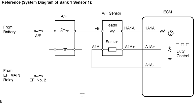
WIRING DIAGRAM
Refer to DTC P2195 .
INSPECTION PROCEDURE
- HINT:
- Intelligent tester only:
- Malfunctioning areas can be identified by performing the Control the Injection Volume for A/F Sensor function provided in the Active Test. The Control the Injection Volume for A/F Sensor function can help to determine whether the Air-Fuel Ratio (A/F) sensor, Heated Oxygen (HO2) sensor and other potential trouble areas are malfunctioning.
The following instructions describe how to conduct the Control the Injection Volume for A/F Sensor operation using the intelligent tester.
- HINT:
| Tester Display (Sensor) | Injection Volume | Status | Voltage |
| AFS B1S1 or AFS B2S1 (A/F) | +25 % | Rich | Less than 3.0 |
| AFS B1S1 or AFS B2S1 (A/F) | -12.5 % | Lean | More than 3.35 |
| O2S B1S2 or O2S B2S2 (HO2) | +25 % | Rich | More than 0.55 |
| O2S B1S2 or O2S B2S2 (HO2) | -12.5 % | Lean | Less than 0.4 |
- NOTICE:
- The Air-Fuel Ratio (A/F) sensor has an output delay of a few seconds and the Heated Oxygen (HO2) sensor has a maximum output delay of approximately 20 seconds.
| Case | A/F Sensor (Sensor 1) Output Voltage | HO2 Sensor (Sensor 2) Output Voltage | Main Suspected Trouble Areas | ||
| 1 | Injection Volume +25 % -12.5 % |  | Injection Volume +25 % -12.5 % | | - |
| Output Voltage More than 3.35 V Less than 3.0 V |  | Output Voltage More than 0.55 V Less than 0.4 V |  | ||
| 2 | Injection Volume +25 % -12.5 % | | Injection Volume +25 % -12.5 % | | A/F sensor A/F sensor heater A/F sensor circuit |
| Output Voltage Almost no reaction |  | Output Voltage More than 0.55 V Less than 0.4 V | | ||
| 3 | Injection Volume +25 % -12.5 % | | Injection Volume +25 % -12.5 % | | HO2 sensor HO2 sensor heater HO2 sensor circuit |
| Output Voltage More than 3.35 V Less than 3.0 V | | Output Voltage Almost no reaction | | ||
| 4 | Injection volume +25 % -12.5 % | | Injection Volume +25 % -12.5 % | | Injector Fuel pressure Gas leakage from exhaust system (Air-fuel ratio extremely lean or rich) |
| Output Voltage Almost no reaction | | Output Voltage Almost no reaction | | ||
- HINT:
| 1.INSPECT AIR FUEL RATIO SENSOR (HEATER RESISTANCE) |
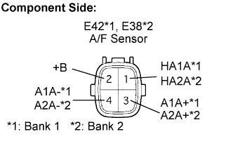
Disconnect the E38 or E42 A/F sensor connector.
Measure the resistance of the A/F sensor connector.
- Standard resistance (Bank 1 sensor 1):
Tester Connection Condition Specified Condition HA1A (1) - +B (2) 20°C (68°F) 1.8 to 3.4 Ω HA1A (1) - A1A- (4) - 10 kΩ or higher
- Standard resistance (Bank 2 sensor 1):
Tester Connection Condition Specified Condition HA2A (1) - +B (2) 20°C (68°F) 1.8 to 3.4 Ω HA2A (1) - A2A- (4) - 10 kΩ or higher
Reconnect the A/F sensor connector.
|
| ||||
| OK | |
| 2.INSPECT A/F HTR RELAY |
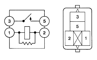
Remove the A/F HTR relay from the engine room J/B and R/B No. 2.
Measure the resistance of the A/F HTR relay.
- Standard resistance:
Tester Connection Specified Condition 3 - 5 10 kΩ or higher 3 - 5 Below 1 Ω
(when battery voltage applied to terminals 1 and 2)
Reinstall the A/F HTR relay.
|
| ||||
| OK | |
| 3.CHECK HARNESS AND CONNECTOR (A/F SENSOR - ECM) |
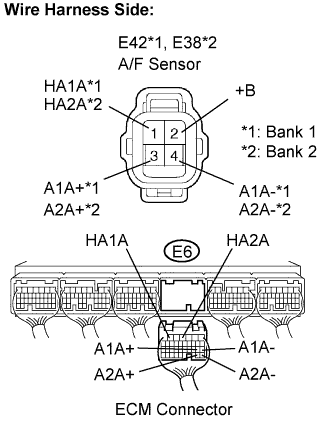
Disconnect the E38 or E42 A/F sensor connector.
Turn the engine switch on (IG).
Measure the voltage between the +B terminal of the A/F sensor connector and body ground.
- Standard voltage:
Tester Connection Specified Condition +B (E38-2) - Body ground 9 to 14 V +B (E42-2) - Body ground 9 to 14 V
Turn the engine switch off.
Disconnect the E6 ECM connector.
Check the resistance of the wire harness side connector.
- Standard resistance (Check for open):
Tester Connection Specified Condition HA1A (E42-1) - HA1A (E6-6) Below 1 Ω A1A+ (E42-3) - A1A+ (E6-18) Below 1 Ω A1A- (E42-4) - A1A- (E6-17) Below 1 Ω HA2A (E38-1) - HA2A (E6-4) Below 1 Ω A2A+ (E38-3) - A2A+ (E6-28) Below 1 Ω A2A- (E38-4) - A2A- (E6-27) Below 1 Ω
- Standard resistance (Check for short):
Tester Connection Specified Condition HA1A (E42-1) or HA1A (E6-6) - Body ground 10 kΩ or higher A1A+ (E42-3) or A1A+ (E6-18) - Body ground 10 kΩ or higher A1A- (E42-4) or A1A- (E6-17) - Body ground 10 kΩ or higher HA2A (E38-1) or HA2A (E6-4) - Body ground 10 kΩ or higher A2A+ (E38-3) or A2A+ (E6-28) - Body ground 10 kΩ or higher A2A- (E38-4) or A2A- (E6-27) - Body ground 10 kΩ or higher
Reconnect the ECM connector.
Reconnect the A/F sensor connector.
|
| ||||
| OK | ||
| ||