Lexus IS250 IS220d GSE20 ALE20 4GR-FSE ENGINE CONTROL SYSTEM
CHECK ANY OTHER DTCS OUTPUT (IN ADDITION TO P2195, P2196, 2197 OR P2198)
READ VALUE OF INTELLIGENT TESTER (OUTPUT VOLTAGE OF A/F SENSOR)
INSPECT AIR FUEL RATIO SENSOR (HEATER RESISTANCE)
CHECK HARNESS AND CONNECTOR (A/F SENSOR - ECM)
PERFORM CONFIRMATION DRIVING PATTERN
CHECK WHETHER DTC OUTPUT RECURS (DTC P2195, P2196, P2197 OR P2198)
CONFIRM IF VEHICLE HAS RUN OUT OF FUEL IN PAST
PERFORM CONFIRMATION DRIVING PATTERN
CHECK WHETHER DTC OUTPUT RECURS (DTC P2195, P2196, P2197 OR P2198)
PERFORM CONFIRMATION DRIVING PATTERN
CHECK WHETHER DTC OUTPUT RECURS (DTC P2195, P2196, P2197 OR P2198)
DTC P2195 Oxygen (A/F) Sensor Signal Stuck Lean (Bank 1 Sensor 1)
DTC P2196 Oxygen (A/F) Sensor Signal Stuck Rich (Bank 1 Sensor 1)
DTC P2197 Oxygen (A/F) Sensor Signal Stuck Lean (Bank 2 Sensor 1)
DTC P2198 Oxygen (A/F) Sensor Signal Stuck Rich (Bank 2 Sensor 1)
DESCRIPTION
- HINT:
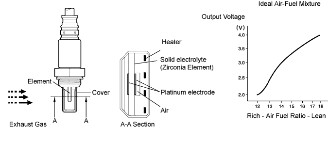
The A/F sensor generates voltage* that corresponds to the actual air-fuel ratio. This sensor voltage is used to provide the ECM with feedback so that it can control the air-fuel ratio. The ECM determines the deviation from the stoichiometric air-fuel ratio level, and regulates the fuel injection time. If the A/F sensor malfunctions, the ECM is unable to control the air-fuel ratio accurately.
The A/F sensor is the planar type and is integrated with the heater, which heats the solid electrolyte (zirconia element). This heater is controlled by the ECM. When the intake air volume is low (the exhaust gas temperature is low), a current flows into the heater to heat the sensor, in order to facilitate accurate oxygen concentration detection. In addition, the sensor and heater portions are narrower than the conventional type. The heat generated by the heater is conducted to the solid electrolyte though the alumina, therefore the sensor activation is accelerated.
In order to obtain a high purification rate of the carbon monoxide (CO), hydrocarbon (HC) and nitrogen oxide (NOx) components in the exhaust gas, a TWC is used. For the most efficient use of the TWC, the air-fuel ratio must be precisely controlled so that it is always close to the stoichiometric level.
*: Value changes inside the ECM. Since the A/F sensor is the current output element, a current is converted to a voltage inside the ECM. Any measurements taken at the A/F sensor or ECM connectors will show a constant voltage.
| DTC No. | DTC Detection Condition | Trouble Area |
| P2195 P2197 | Conditions (a) and (b) continue for 2 seconds or more (2 trip detection logic): (a) Air-Fuel Ratio (A/F) sensor voltage more than 3.8 V (b) Heated Oxygen (HO2) sensor voltage 0.15 V or more | Open or short in A/F sensor (bank 1, 2 sensor 1) circuit A/F sensor (bank 1, 2 sensor 1) A/F sensor (bank 1, 2 sensor 1) heater A/F HTR relay A/F sensor heater and relay circuits Air induction system Fuel pressure Injector ECM |
| P2195 P2197 | While fuel-cut operation performed (during vehicle deceleration), air-fuel ratio (A/F) sensor current 3.6 mA or more for 3 seconds (2 trip detection logic) | A/F sensor ECM |
| P2196 P2198 | Conditions (a) and (b) continue for 2 seconds or more (2 trip detection logic): (a) A/F sensor voltage less than 2.8 V (b) HO2 sensor voltage less than 0.85 V | Open or short in A/F sensor (bank 1, 2 sensor 1) circuit A/F sensor (bank 1, 2 sensor 1) A/F sensor (bank 1, 2 sensor 1) heater A/F HTR relay A/F sensor heater and relay circuits Air induction system Fuel pressure Injector ECM |
| P2196 P2198 | While fuel-cut operation performed (during vehicle deceleration), air-fuel ratio (A/F) sensor current 0.4 mA for 3 seconds (2 trip detection logic) | A/F sensor ECM |
- HINT:
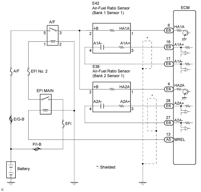
WIRING DIAGRAM
CONFIRMATION DRIVING PATTERN
This confirmation driving pattern is used in steps 2, 4, 7, 17 and 21 of the following diagnostic troubleshooting procedure when using an intelligent tester.
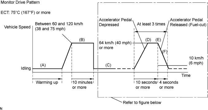
- HINT:
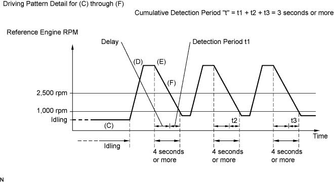
- Fuel-cut is performed when the following conditions are met:
- HINT:
- Completion of all A/F sensor monitors is required to change the value in TEST RESULT.
- CAUTION:
- Strictly observe posted speed limits, traffic laws, and road conditions when performing these drive patterns.
INSPECTION PROCEDURE
- HINT:
- Malfunctioning areas can be identified by performing the Control the Injection Volume for A/F Sensor function provided in the Active Test. The Control the Injection Volume for A/F Sensor function can help to determine whether the Air-fuel Ratio (A/F) sensor, Heated Oxygen (HO2) sensor and other potential trouble areas are malfunctioning.
The following instructions describe how to conduct the Control the Injection Volume for A/F Sensor operation using the intelligent tester.
- HINT:
| Tester Display (Sensor) | Injection Volume | Status | Voltage |
| AFS B1S1 or AFS B2S1 (A/F) | +25 % | Rich | Less than 3.0 |
| AFS B1S1 or AFS B2S1 (A/F) | -12.5 % | Lean | More than 3.35 |
| O2S B1S2 or O2S B2S2 (HO2) | +25 % | Rich | More than 0.55 |
| O2S B1S2 or O2S B2S2 (HO2) | -12.5 % | Lean | Less than 0.4 |
- NOTICE:
- The Air-Fuel Ratio (A/F) sensor has an output delay of a few seconds and the HO2S (sensor 2) output has a maximum of 20 seconds of delay.
| Case | A/F Sensor (Sensor 1) Output Voltage | HO2 Sensor (Sensor 2) Output Voltage | Main Suspected Trouble Areas | ||
| 1 | Injection Volume +25 % -12.5 % |  | Injection Volume +25 % -12.5 % | | - |
| Output Voltage More than 3.35 V Less than 3.0 V |  | Output Voltage More than 0.55 V Less than 0.4 V |  | ||
| 2 | Injection Volume +25 % -12.5 % | | Injection Volume +25 % -12.5 % | | A/F sensor A/F sensor heater A/F sensor circuit |
| Output Voltage Almost no reaction |  | Output Voltage More than 0.55 V Less than 0.4 V | | ||
| 3 | Injection Volume +25 % -12.5 % | | Injection Volume +25 % -12.5 % | | HO2 sensor HO2 sensor heater HO2 sensor circuit |
| Output Voltage More than 3.35 V Less than 3.0 V | | Output Voltage Almost no reaction | | ||
| 4 | Injection volume +25 % -12.5 % | | Injection Volume +25 % -12.5 % | | Injector Fuel pressure Gas leakage from exhaust system (Air-fuel ratio extremely lean or rich) |
| Output Voltage Almost no reaction | | Output Voltage Almost no reaction | | ||
- HINT:
| 1.CHECK ANY OTHER DTCS OUTPUT (IN ADDITION TO P2195, P2196, 2197 OR P2198) |
Connect the intelligent tester to the DLC3.
Turn the engine switch on (IG).
Turn the tester ON
Enter the following menus: Power train / Engine / DTC.
Read DTCs.
- Result:
Display (DTC Output) Proceed to P2195, P2196, P2197, or P2198 A P2195, P2196, P2197, or P2198 and other DTCs B
- HINT:
- If any DTCs other than P2195, P2196, P2197 or P2198 are output, troubleshoot those DTCs first.
|
| ||||
| OK | |
| 3.INSPECT AIR FUEL RATIO SENSOR (HEATER RESISTANCE) |
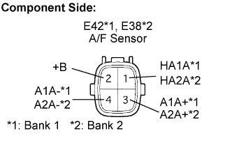
Disconnect the E38 or E42 A/F sensor connector.
Measure the resistance of the A/F sensor connector.
- Standard resistance (Bank 1 sensor 1):
Tester Connection Condition Specified Condition HA1A (1) - +B (2) 20°C (68°F) 1.8 Ω to 3.4 Ω HA1A (1) - A1A- (4) - 10 kΩ or higher
- Standard resistance (Bank 2 sensor 1):
Tester Connection Condition Specified Condition HA2A (1) - +B (2) 20°C (68°F) 1.8 Ω to 3.4 Ω HA2A (1) - A2A- (4) - 10 kΩ or higher
Reconnect the A/F sensor connector.
|
| ||||
| A | |
| 14.REPLACE AIR FUEL RATIO SENSOR |
| NEXT | |
| 15.PERFORM CONFIRMATION DRIVING PATTERN |
| NEXT | |
| 16.CHECK WHETHER DTC OUTPUT RECURS (DTC P2195, P2196, P2197 OR P2198) |
Connect the intelligent tester to the DLC3.
Turn the engine switch on (IG) and turn the tester ON.
Read DTCs using the intelligent tester.
Enter the following menus: Power train / Engine / DTC.
- Result:
Display (DTC Output) Proceed to No output A P2195, P2196, P2197 or P2198 (A/F sensor pending DTCs) B
|
| ||||
| A | ||
| ||