Lexus IS250 IS220d GSE20 ALE20 4GR-FSE ENGINE CONTROL SYSTEM
INSPECT THROTTLE BODY (RESISTANCE OF THROTTLE CONTROL MOTOR)
CHECK HARNESS AND CONNECTOR (THROTTLE CONTROL MOTOR - ECM)
INSPECT THROTTLE BODY (VISUALLY CHECK THROTTLE VALVE)
INSPECT THROTTLE BODY (THROTTLE VALVE)
DTC P2102 Throttle Actuator Control Motor Circuit Low
DTC P2103 Throttle Actuator Control Motor Circuit High
DESCRIPTION
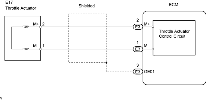
The throttle actuator is operated by the ECM and opens and closes the throttle valve using gears.
The opening angle of the throttle valve is detected by the Throttle Position (TP) sensor, which is mounted on the throttle body. The TP sensor provides feedback to the ECM. This feedback allows the ECM to appropriately control the throttle actuator and monitor the throttle opening angle as the ECM responds to driver inputs.
- HINT:
- This ETCS (Electronic Throttle Control System) does not use a throttle cable.
| DTC No. | DTC Detection Condition | Trouble Area |
| P2102 | Conditions (a) and (b) continue for 2.0 seconds (1 trip detection logic): (a) Throttle actuator duty ratio 80 % or more (b) Throttle actuator current 0.5 A or less | Open in throttle actuator circuit Throttle actuator ECM |
| P2103 | Either of following conditions met: Hybrid IC diagnosis signal fail Hybrid IC current limiter port fail | Open in throttle actuator circuit Throttle actuator ECM |
FAIL-SAFE
When either of these DTCs, as well as other DTCs relating to ETCS (Electronic Throttle Control System) malfunctions, is set, the ECM enters fail-safe mode. During fail-safe mode, the ECM cuts the current to the throttle actuator off, and the throttle valve is returned to a 6° throttle angle by the return spring. The ECM then adjusts the engine output by controlling the fuel injection (intermittent fuel-cut) and ignition timing, in accordance with the accelerator pedal opening angle, to allow the vehicle to continue at a minimal speed. If the accelerator pedal is depressed firmly and gently, the vehicle can be driven slowly.
Fail-safe mode continues until a pass condition is detected, and the engine switch is then turned off.
WIRING DIAGRAM
INSPECTION PROCEDURE
- HINT:
| 1.INSPECT THROTTLE BODY (RESISTANCE OF THROTTLE CONTROL MOTOR) |
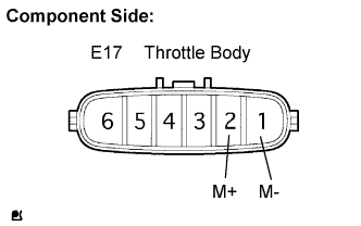
Disconnect the E17 throttle body connector.
Measure the resistance of the throttle control motor.
- Standard resistance:
Tester Connection Condition Specified Condition M+ (E17-2) - M- (E17-1) 20°C (68°F) 0.3 to 100 Ω
Reconnect the throttle body connector.
|
| ||||
| OK | |
| 2.CHECK HARNESS AND CONNECTOR (THROTTLE CONTROL MOTOR - ECM) |
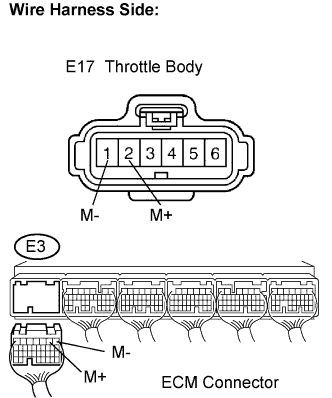
Disconnect the E17 throttle body connector.
Disconnect the E3 ECM connector.
Measure the resistance of the wire harness side connector.
- Standard resistance (Check for open):
Tester Connection Specified Condition M+ (E17-2) - M+ (E3-2) Below 1 Ω M- (E17-1) - M- (E3-1) Below 1 Ω
- Standard resistance (Check for short):
Tester Connection Specified Condition M+ (E17-2) or M+ (E3-2) - Body ground 10 kΩ or higher M- (E17-1) or M- (E3-1) - Body ground 10 kΩ or higher
Reconnect the throttle body connector.
Reconnect the ECM connector.
|
| ||||
| OK | |
| 3.INSPECT THROTTLE BODY (VISUALLY CHECK THROTTLE VALVE) |
Check for foreign objects between the throttle valve and the housing.
|
| ||||
| OK | |
| 4.INSPECT THROTTLE BODY (THROTTLE VALVE) |
Check if the throttle valve opens and closes smoothly.
|
| ||||
| OK | ||
| ||