Lexus IS250 IS220d GSE20 ALE20 4GR-FSE ENGINE CONTROL SYSTEM
CHECK STOP LIGHT (STOP LIGHT OPERATION)
READ VALUE OF INTELLIGENT TESTER (STP SIGNAL AND ST1 - VOLTAGE)
INSPECT STOP LIGHT SWITCH ASSEMBLY
CHECK ECM (STP, ST1 - VOLTAGE)
DTC P0504 Brake Switch "A" / "B" Correlation
DTC P0724 Brake Switch "B" Circuit High
DESCRIPTION
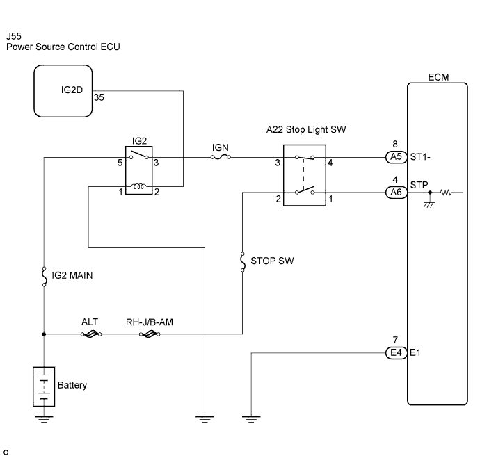
The stop light switch is a duplex system that transmits two signals: STP and ST1-. These two signals are used by the ECM to monitor whether or not the brake system is working properly. If the signals, which indicate the brake pedal is being depressed and released, are detected simultaneously, the ECM interprets this as a malfunction in the stop light switch and sets the DTC.
- HINT:
- The normal conditions are as shown in the table below. The signals can be read using an intelligent tester.
| Signal | Brake Pedal Released | In Transition | Brake Pedal Depressed |
| STP | OFF | ON | ON |
| ST1- | ON | ON | OFF |
| DTC No. | DTC Detection Condition | Trouble Area |
| P0504 | Conditions (a), (b) and (c) continue for 0.5 seconds or more (1 trip detection logic): (a) Engine switch on (IG) (b) Brake pedal released (c) STP signal OFF when ST1- signal OFF | Short in stop light switch signal circuit Stop light switch ECM |
| P0724 | The stop light switch remains ON even when the vehicle is driven in a STOP (less than 3 km/h (2 mph)) and GO (30 km/h (19 mph) or more) fashion 5 times. (2 trip detection logic) | Short in stop light switch signal circuit Stop light switch ECM |
WIRING DIAGRAM
INSPECTION PROCEDURE
- HINT:
- Read freeze frame data using the intelligent tester. Freeze frame data records the engine conditions when malfunctions are detected. When troubleshooting, freeze frame data can help determine if the vehicle was running or stopped, if the engine was warmed up or not, if the air-fuel ratio was lean or rich, and other data from the time the malfunction occurred .
| 1.CHECK STOP LIGHT (STOP LIGHT OPERATION) |
Check whether the stop lights turn on and off normally when the brake pedal is depressed and released.
- OK:
- Stop lights turn ON when brake pedal is depressed.
|
| ||||
| OK | |
| 2.READ VALUE OF INTELLIGENT TESTER (STP SIGNAL AND ST1 - VOLTAGE) |
Connect the intelligent tester to the DLC3.
Turn the engine switch on (IG) and turn the tester ON.
Enter the following menus: Power train / Engine / Data List / Stop Light Switch.
Check the STP signal when the brake pedal is depressed and released.
- OK:
Brake Pedal Operation Specified Condition Depressed STP signal ON Released STP signal OFF
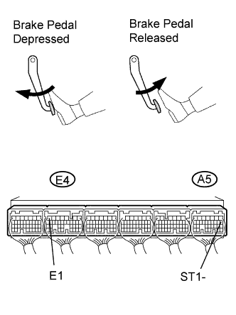
Measure the voltage of the A5 and E4 ECM connectors.
- Standard voltage:
Tester Connection Brake Pedal Operation Specified Condition ST1- (A5-8) - E1 (E4-7) Depressed Below 1.5 V ST1- (A5-8) - E1 (E4-7) Released 7.5 to 14 V
|
| ||||
| NG | |
| 3.INSPECT STOP LIGHT SWITCH ASSEMBLY |
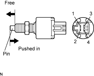
Remove the stop light switch assembly.
Measure the resistance of the stop light switch.
- Standard resistance:
Switch Position Tester Connection Specified Condition Switch pin free 1 - 2 Below 1 Ω Switch pin free 3 - 4 10 kΩ or higher Switch pin pushed in 1 - 2 10 kΩ or higher Switch pin pushed in 3 - 4 Below 1 Ω
Reinstall the stop light switch assembly.
|
| ||||
| OK | |
| 4.CHECK ECM (STP, ST1 - VOLTAGE) |
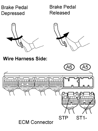
Disconnect the A5 and A6 ECM connectors.
Measure the voltage of the A5 and A6 ECM connectors.
- Standard voltage:
Tester Connection Brake Pedal Operation Specified Condition STP (A6-4) - Body ground Depressed 9 to 14 V STP (A6-4) - Body ground Released 0 to 3 V ST1- (A5-8) - Body ground Depressed 0 to 3 V ST1- (A5-8) - Body ground Released 9 to 14 V
|
| ||||
| OK | ||
| ||