Lexus IS250 IS220d GSE20 ALE20 4GR-FSE ENGINE CONTROL SYSTEM
CRANKSHAFT POSITION SENSOR - INSTALLATION
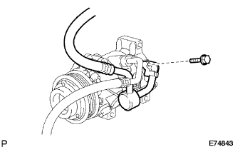
| 1. INSTALL CRANKSHAFT POSITION SENSOR |
Apply a coat of engine oil to an O-ring of the crankshaft position sensor.
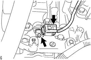
Install the crankshaft position sensor with the bolt.
- Torque:
- 10 N*m{ 102 kgf*cm, 7 ft.*lbf}
Connect the crankshaft position sensor connector.
| 2. INSTALL COMPRESSOR AND MAGNETIC CLUTCH |
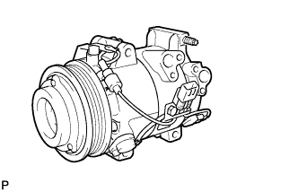
Temporarily install the compressor and magnetic clutch onto the stud bolt.
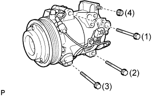
Install the compressor and magnetic clutch with the 3 bolts and nut.
- Torque:
- 25 N*m{ 255 kgf*cm, 18 ft.*lbf}
- NOTICE:
- Tighten the bolts in the order shown in the illustration to install the compressor and magnetic clutch.
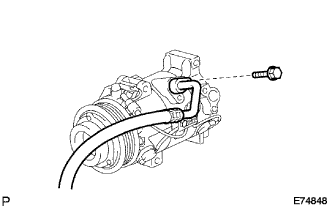
| 3. INSTALL DISCHARGE HOSE SUB-ASSEMBLY |
Remove the attached vinyl tape from the hose.
Apply sufficient compressor oil (ND-OIL 8) to a new O-ring and the fitting surface of the compressor and magnetic clutch.
- Compressor oil:
- ND-OIL 8 or equivalent
Install the O-ring onto the discharge hose sub-assembly.
Install the discharge hose sub-assembly onto the compressor and magnetic clutch with the bolt.
- Torque:
- 9.8 N*m{ 100 kgf*cm, 87 in.*lbf}
| 4. INSTALL NO. 1 COOLER REFRIGERANT SUCTION HOSE |
Remove the attached vinyl tape from the hose.
Apply sufficient compressor oil to a new O-ring and the fitting surface of the compressor and magnetic clutch.
- Compressor oil:
- ND-OIL 8 or equivalent
Install the O-ring onto the No.1 cooler refrigerant suction hose.
Install the No. 1 cooler refrigerant suction hose onto the compressor and magnetic clutch with the bolt.
- Torque:
- 9.8 N*m{ 100 kgf*cm, 87 in.*lbf}
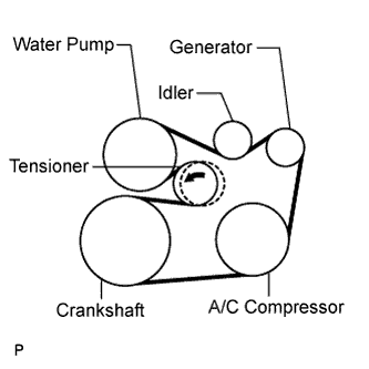
| 5. INSTALL V-RIBBED BELT |
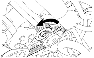
Install the V-ribbed belt.
While turning the belt tensioner counterclockwise, remove the bar.
- NOTICE:
If it is difficult to install the V-ribbed belt, perform the following procedure.
Put the V-ribbed belt on every part except the tensioner pulley as shown in the illustration.
While releasing the belt tension by turning the belt tensioner counterclockwise, put the V-ribbed belt on the tensioner pulley.
- NOTICE:
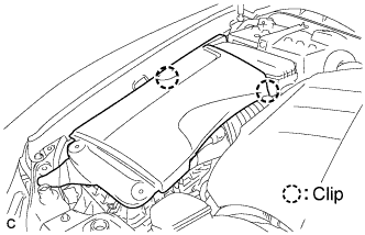
| 6. INSTALL ENGINE UNDER COVER REAR LH |
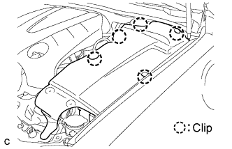
Install the side cover with the 5 clips.
| 7. INSTALL ENGINE UNDER COVER |
| 8. INSTALL NO. 1 INLET AIR CLEANER |
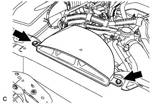
Install the inlet air cleaner with the bolt.
- Torque:
- 5.0 N*m{ 51 kgf*cm, 44 in.*lbf}
| 9. INSTALL V-BANK COVER SUB-ASSEMBLY |
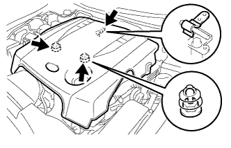
Engage the 2 clips on the front of the cover, and then engage the clip on the rear to install the V-bank cover.
- NOTICE:
| 10. INSTALL ENGINE ROOM SIDE COVER LH |
Install the side cover with the 5 clips.
| 11. INSTALL ENGINE ROOM SIDE COVER RH |
Install the side cover with the 2 clips.
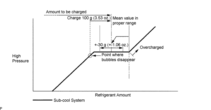
| 12. CHARGE REFRIGERANT |
Perform vacuum purging using a vacuum pump.
Charge refrigerant HFC-134a (R134a).
- Standard:
- 430 +- 30 g (15.17 +- 1.06 oz.)
- SST
- 07110-58060(07117-58060,07117-58070,07117-58080,07117-58090,07117-78050,07117-88060,07117-88070,07117-88080)
- NOTICE:
| 13. WARM UP ENGINE |
| 14. CHECK FOR LEAKAGE OF REFRIGERANT |
After recharging the refrigerant gas, check for refrigerant gas leakage using a halogen leak detector.
Perform the operation under the following conditions:
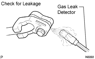
Using a gas leak detector, check the refrigerant line for leakage.
If a gas leak is not detected on the drain hose, remove the blower motor control (blower resistor) from the cooling unit. Insert the gas leak detector sensor into the unit and perform the test.
Disconnect the connector and leave the pressure switch on for approximately 20 minutes. Bring the gas leak detector close to the pressure switch and perform the test.