Lexus IS250 IS220d GSE20 ALE20 4GR-FSE COOLING
WATER PUMP - INSTALLATION
| 1. INSTALL WATER PUMP ASSEMBLY |
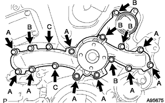
Install a new water pump gasket and the water pump assembly with the 16 bolts.
- Torque:
- 21 N*m{ 214 kgf*cm, 15 ft.*lbf}for bolts A
- 9.1 N*m{ 93 kgf*cm, 81 in.*lbf}for bolts B and C
- NOTICE:
| 2. INSTALL NO. 2 IDLER PULLEY SUB-ASSEMBLY |
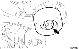
Install the pulley and cover plate with the bolt.
- Torque:
- 43 N*m{ 438 kgf*cm, 32 ft.*lbf}
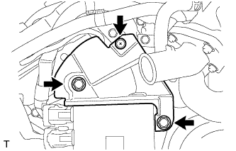
| 3. INSTALL WATER INLET |
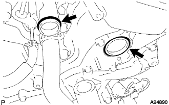
Install a new water inlet housing gasket No.1 and water outlet pipe O-ring.
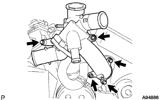
Install the water inlet with the 4 bolts and nut.
- Torque:
- 10 N*m{ 102 kgf*cm, 7 ft.*lbf}
- NOTICE:
- Be careful not to allow the O-ring to get caught between parts.
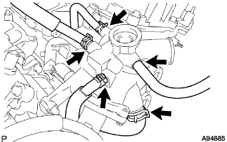
Connect the 5 hoses.
| 4. INSTALL WATER PUMP PULLEY |
Temporarily install the pulley with the 4 bolts.
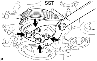
Using SST, hold the pulley and tighten the 4 bolts.
- SST
- 09960-10010(09962-01000,09963-00700)
- Torque:
- 21 N*m{ 214 kgf*cm, 15 ft.*lbf}
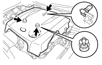
| 5. INSTALL NO. 2 ENGINE COVER |
Install the No. 2 engine cover with the 3 clips.
Connect the clamp.
| 6. INSTALL INJECTOR DRIVER |
Install the injector driver with the bolt and 2 nuts.
- Torque:
- 10 N*m{ 102 kgf*cm, 7 ft.*lbf}
| 7. INSTALL NO. 1 ENGINE COVER |
Install the No. 1 engine cover with the 3 clips.
| 8. CONNECT RADIATOR HOSE |
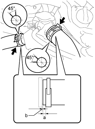
Connect the radiator inlet hose and radiator outlet hose to the radiator assembly and secure them with the clips.
- HINT:
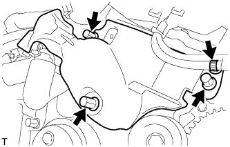
| 9. INSTALL V-RIBBED BELT TENSIONER ASSEMBLY |
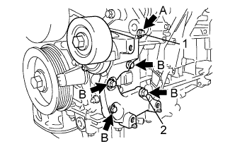
Temporarily install the V-ribbed belt tensioner with the 5 bolts.
- Each bolt length is as follows:
Mark Specified Length A 70 mm (2.76 in.) B 35 mm (1.38 in.)
Install the V-ribbed belt tensioner by tightening the bolt 1 and bolt 2 in the order shown in the illustration.
- Torque:
- 43 N*m{ 439 kgf*cm, 32 ft.*lbf}
Tighten the other bolts.
- Torque:
- 43 N*m{ 439 kgf*cm, 32 ft.*lbf}
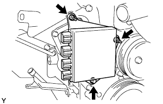
| 10. INSTALL COMPRESSOR AND MAGNETIC CLUTCH |
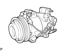
Temporarily install the compressor and magnetic clutch onto the stud bolt.
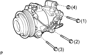
Install the compressor and magnetic clutch with the 3 bolts and nut.
- Torque:
- 25 N*m{ 255 kgf*cm, 18 ft.*lbf}
- NOTICE:
- Tighten the bolts in the order shown in the illustration to install the compressor and magnetic clutch.
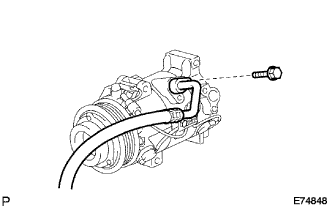
| 11. CONNECT DISCHARGE HOSE SUB-ASSEMBLY |
Remove the attached vinyl tape from the hose.
Apply sufficient compressor oil (ND-OIL 8) to a new O-ring and the fitting surface of the compressor and magnetic clutch.
- Compressor oil:
- ND-OIL 8 or equivalent
Install the O-ring onto the discharge hose sub-assembly.
Install the discharge hose sub-assembly onto the compressor and magnetic clutch with the bolt.
- Torque:
- 9.8 N*m{ 100 kgf*cm, 87 in.*lbf}
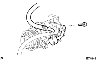
| 12. CONNECT NO. 1 COOLER REFRIGERANT SUCTION HOSE |
Remove the attached vinyl tape from the hose.
Apply sufficient compressor oil to a new O-ring and the fitting surface of the compressor and magnetic clutch.
- Compressor oil:
- ND-OIL 8 or equivalent
Install the O-ring onto the No.1 cooler refrigerant suction hose.
Install the No. 1 cooler refrigerant suction hose onto the compressor and magnetic clutch with the bolt.
- Torque:
- 9.8 N*m{ 100 kgf*cm, 87 in.*lbf}
| 13. INSTALL V-RIBBED BELT |
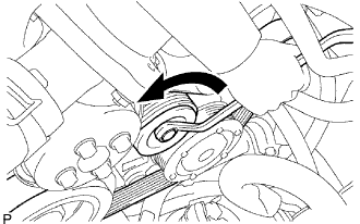
Install the V-ribbed belt.
While turning the belt tensioner counterclockwise, remove the bar.
- NOTICE:
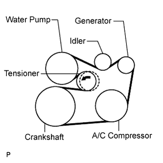
If it is difficult to install the V-ribbed belt, perform the following procedure.
Put the V-ribbed belt on every part except the tensioner pulley as shown in the illustration.
While releasing the belt tension by turning the belt tensioner counterclockwise, put the V-ribbed belt on the tensioner pulley.
- NOTICE:
| 14. INSTALL REAR ENGINE UNDER COVER LH |
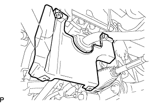
Install the engine under cover rear LH with the bolt.
| 15. INSTALL ENGINE UNDER COVER |
| 16. INSTALL NO. 1 INLET AIR CLEANER |
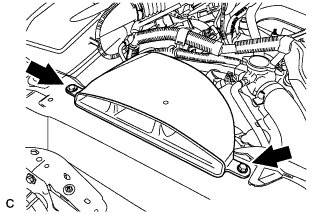
Install the inlet air cleaner with the bolt.
- Torque:
- 5.0 N*m{ 51 kgf*cm, 44 in.*lbf}
| 17. CONNECT CABLE TO NEGATIVE BATTERY TERMINAL |
- Torque:
- 5.4 N*m{ 55 kgf*cm, 48 in.*lbf}
| 18. ADD ENGINE OIL |
Add new oil.
- Specification:
Item Capacity Drain and refill with oil filter change 6.3 liters (6.7 US qts, 5.5 Imp. qts) Drain and refill without oil filter change 5.9 liters (6.2 US qts, 5.2 Imp. qts) Dry fill 7.2 liters (7.6 US qts, 6.3 Imp. qts)
Install the oil filter cap.
| 19. ADD ENGINE COOLANT |
Tighten all the plugs and fill the radiator with TOYOTA Super Long Life Coolant (SLLC).
- Torque:
- 13 N*m{ 130 kgf*cm, 9 ft.*lbf}for cylinder block drain cock plug
Add engine coolant.
- Specified capacity:
- 9.1 liters (9.6 US qts, 8.0 lmp. qts)
- HINT:
Slowly pour coolant into the radiator reservoir until it reaches the FULL line.
Press the inlet and outlet radiator hoses several times by hand, and then check the level of the coolant.
If the coolant level is low, add coolant.
Install the radiator cap and reservoir cap.
Bleed air from the cooling system.
- NOTICE:
- Before starting the engine to warm up the engine, turn the A/C switch OFF.
Warm up the engine until the thermostat opens. While the thermostat is open, circulate the coolant for several minutes.
- HINT:
- The thermostat open timing can be confirmed by pressing the inlet radiator hose by hand, and checking when the engine coolant starts to flow inside the hose.
- NOTICE:
- When pressing the radiator hoses:
Maintain the engine speed at 2,000 to 2,500 rpm.
Press the inlet and outlet radiator hoses several times by hand to bleed air.
- NOTICE:
- When pressing the radiator hoses:
Stop the engine, and wait until the engine coolant cools down to ambient temperature.
- NOTICE:
- Do not remove the radiator cap while the engine and radiator are still hot. Pressurized, hot engine coolant and steam may be released and cause serious burns.
Check the coolant level in the radiator reservoir.
If the coolant level is low, add SLLC to the radiator reservoir FULL line.
| 20. CHECK FOR ENGINE OIL LEAKS |
Start the engine. Make sure that no oil leaks from the connection point of the oil filter cap.
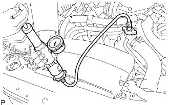
| 21. CHECK FOR ENGINE COOLANT LEAKAGE |
- NOTICE:
- Before performing each inspection, turn the A/C switch OFF.
- CAUTION:
- Do not remove the radiator cap while the engine and radiator are still hot. Pressurized, hot engine coolant and steam may be released and cause serious burns.
Fill the radiator with coolant and attach a radiator cap tester.
Warm up the engine.
Using a radiator cap tester, increase the pressure inside the radiator to 118 kPa (1.2 kgf*cm2, 17 psi), and check that the pressure does not drop.
If the pressure drops, check the hoses, radiator and water pump for leaks. If no external leaks are found, check the heater core, cylinder block and cylinder head.
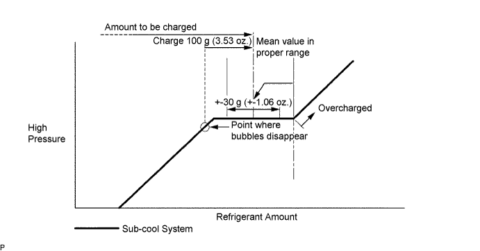
| 22. CHARGE REFRIGERANT |
Perform vacuum purging using a vacuum pump.
Charge refrigerant HFC-134a (R134a).
- Standard:
- 430 +- 30 g (15.17 +- 1.06 oz.)
- SST
- 07110-58060(07117-58060,07117-58070,07117-58080,07117-58090,07117-78050,07117-88060,07117-88070,07117-88080)
- NOTICE:
| 23. START ENGINE |
| 24. CHECK FOR LEAKAGE OF REFRIGERANT |
After recharging the refrigerant gas, check for refrigerant gas leakage using a halogen leak detector.
Perform the operation under the following conditions:
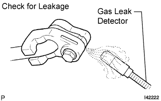
Using a gas leak detector, check the refrigerant line for leakage.
If a gas leak is not detected on the drain hose, remove the blower motor control (blower resistor) from the cooling unit. Insert the gas leak detector sensor into the unit and perform the test.
Disconnect the connector and leave the pressure switch on for approximately 20 minutes. Bring the gas leak detector close to the pressure switch and perform the test.
| 25. INSTALL V-BANK COVER SUB-ASSEMBLY |
Engage the 2 clips on the front of the cover, and then engage the clip on the rear to install the V-bank cover.
- NOTICE:
| 26. INSTALL COOL AIR INTAKE DUCT SEAL |
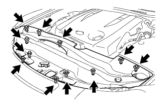
Install the intake duct seal with the 11 clips.