Dtc B2282 Vehicle Speed Signal Malfunction
Lexus IS250 IS220d GSE20 ALE20 2AD-FHV STARTING
DESCRIPTION
WIRING DIAGRAM
INSPECTION PROCEDURE
CHECK OPERATION OF SPEEDOMETER
CHECK DTC OUTPUT (MULTIPLEX NETWORK COMMUNICATION SYSTEM (BEAN))
CHECK CONNECTORS
CHECK WIRE HARNESS (POWER SOURCE CONTROL ECU - BODY GROUND)
CHECK WIRE HARNESS (POWER SOURCE CONTROL ECU - COMBINATION METER)
READ VALUE OF INTELLIGENT TESTER (VEHICLE SPEED SIGNAL)
INSPECT POWER SOURCE CONTROL ECU (SPEED SIGNAL)
DTC B2282 Vehicle Speed Signal Malfunction
DESCRIPTION
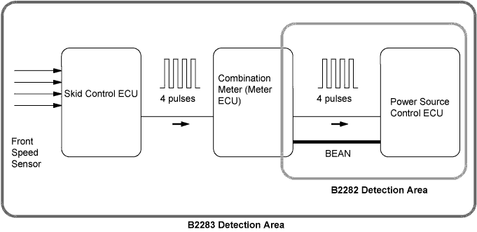
The power source control ECU and the combination meter are connected by a cable and the BEAN. DTC B2282 is output when: 1) the cable information and BEAN information are inconsistent; and 2) a malfunction is detected between the vehicle speed sensor and combination meter.
- When the power source control ECU is replaced with a new one and the negative (-) battery terminal is connected, the power source mode becomes the IG-ON mode. When the battery is removed and reinstalled, the power source mode that was selected when the battery was removed is restored.
| DTC No. | DTC Detection Condition | Trouble Area |
| B2282 |
When both conditions below are met:
Cable for BEAN information between the power source control ECU and the combination meter are inconsistent
Malfunction is detected between the vehicle speed sensor and the combination meter
|
Multiplex communication system
Combination meter system
Power source control ECU
Wire harness or connector
|
WIRING DIAGRAM
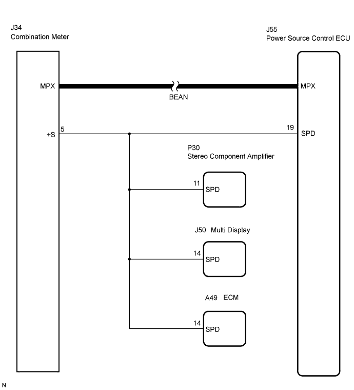
A voltage of 12 V or 5 V is output from each ECU and then input to the combination meter. The signal is changed to a pulse signal at the transistor in the combination meter. Each ECU controls the respective system based on the pulse signal.
If a short occurs in an ECU, all systems in the diagram below will not operate normally.
INSPECTION PROCEDURE
| 1.CHECK OPERATION OF SPEEDOMETER |
Drive the vehicle and check if the function of the speedometer in the combination meter is normal.
- OK:
- Actual vehicle speed and the speed indicated on the speedometer are the same.
- The vehicle speed sensor is functioning normally when the indication on the speedometer is normal.
| | REPLACE COMBINATION METER |
|
|
| 2.CHECK DTC OUTPUT (MULTIPLEX NETWORK COMMUNICATION SYSTEM (BEAN)) |
Check for the multiplex network communication system DTCs B1210, B1214 and B1215.
- If the DTCs for the multiplex network communication system malfunction are output, inspect those DTCs first .
| | GO TO MULTIPLEX COMMUNICATION SYSTEM |
|
|
Check that the connectors are securely connected and the terminals are not deformed or loose.
- OK:
- The connectors are securely connected and the terminals are not deformed or loose.
| | REPAIR OR REPLACE CONNECTORS |
|
|
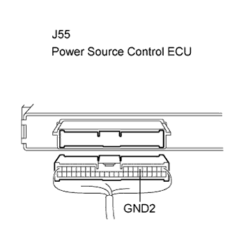
| 4.CHECK WIRE HARNESS (POWER SOURCE CONTROL ECU - BODY GROUND) |
Disconnect the ECU connector.
Measure the resistance according to the value(s) in the table below.
- Standard resistance:
| Tester Connection (Symbols) | Condition | Specified Condition |
| J55-6 (GND2) - Body ground | Always | Below 1Ω |
| | REPAIR OR REPLACE HARNESS OR CONNECTOR |
|
|
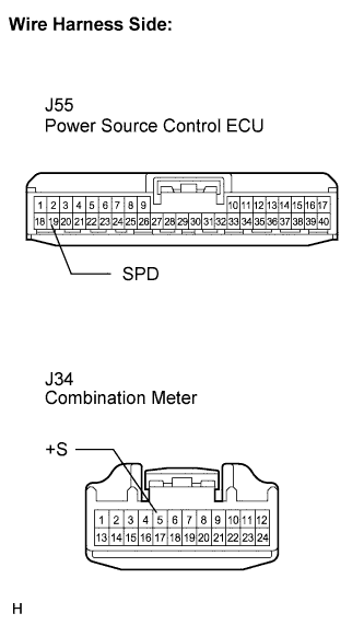
| 5.CHECK WIRE HARNESS (POWER SOURCE CONTROL ECU - COMBINATION METER) |
Disconnect the J34 meter connector.
Measure the resistance according to the value(s) in the table below.
- Standard resistance:
| Tester Connection (Symbols) | Condition | Specified Condition |
| J55-19 (SPD) - J34-5 (+S) | Always | Below 1 Ω |
| J55-19 (SPD) or J34-5 (+S) - Body ground | Always | 10 kΩ or higher |
- If the result of the inspection for a short circuit is not as specified, there may be a short in the ECU.
| | REPAIR OR REPLACE HARNESS, CONNECTOR OR EACH ECU |
|
|
| 6.READ VALUE OF INTELLIGENT TESTER (VEHICLE SPEED SIGNAL) |
Reconnect the connectors.
Connect the intelligent tester to the DLC3.
Turn the engine switch on (IG).
Check the DATA LIST for proper functioning of the vehicle speed signal.
Power Source Control:| Item | Measurement Item/Display (Range) | Normal Condition | Diagnostic Note |
| Vehicle Spd Sig | Vehicle speed signal/ STOP or RUN | STOP: Vehicle is stopped
RUN: Vehicle is running | - |
- OK:
- STOP (vehicle is stopped) and RUN (vehicle is running) appear on the screen.
| | REPLACE COMBINATION METER |
|
|
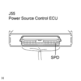
| 7.INSPECT POWER SOURCE CONTROL ECU (SPEED SIGNAL) |
Check the input signal waveform.
Reconnect the connectors.
Remove the combination meter assembly with connector(s) still connected.
Connect the oscilloscope to the terminals J55-19 (SPD) and body ground.
Turn the engine switch on (IG).
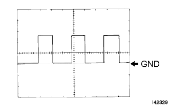
Check the signal waveform according to the condition(s) in the table below.
| Item | Condition |
| Tool setting | 5 V/DIV., 10 ms./DIV. |
| Vehicle condition | Driving at approx. 20 km/h (12 mph) |
- OK:
- The waveform is displayed as shown in the illustration.
- As the vehicle speed increases, the cycle of the signal waveform narrows.
| | REPLACE COMBINATION METER |
|
|
| OK | |
| |
| REPLACE POWER SOURCE CONTROL ECU |
|