Dtc B2275 Stsw Monitor Malfunction
Lexus IS250 IS220d GSE20 ALE20 2AD-FHV STARTING
DESCRIPTION
WIRING DIAGRAM
INSPECTION PROCEDURE
CHECK FOR DTCS
INSPECT FUSE (AM2)
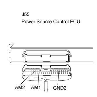
CHECK CONNECTORS
CHECK WIRE HARNESS (POWER SOURCE CONTROL ECU - BATTERY AND BODY GROUND)
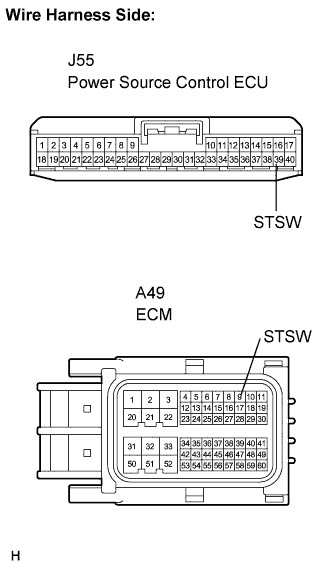
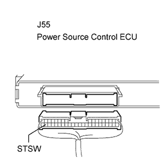
CHECK WIRE HARNESS (POWER SOURCE CONTROL ECU - ECM)
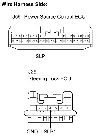
CHECK WIRE HARNESS (STEERING LOCK ECU - POWER SOURCE CONTROL ECU AND BODY GROUND)
INSPECT POWER SOURCE CONTROL ECU
INSPECT STEERING LOCK ECU
INSPECT POWER SOURCE CONTROL ECU
DTC B2275 STSW Monitor Malfunction
DESCRIPTION
This DTC is output when there is an open, short, or any other problem in the engine start request output circuit inside the power source control ECU or in the external circuit.
- When the power source control ECU is replaced with a new one and the negative (-) battery terminal is connected, the power source mode becomes the IG-ON mode. When the battery is removed and reinstalled, the power source mode that was selected when the battery was removed is restored.
| DTC No. | DTC Detection Condition | Trouble Area |
| B2275 |
ST output circuit (engine starting request signal circuit) inside power source control ECU or other related circuit is malfunctioning |
AM2 fuse
ECM
Steering lock ECU
Power source control ECU
Wire harness or connector
|
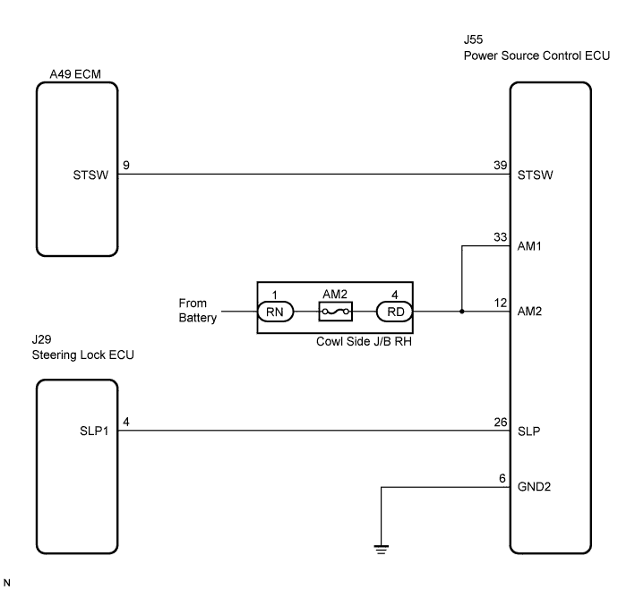
WIRING DIAGRAM
INSPECTION PROCEDURE
After all DTCs are cleared, turn the engine switch on (IG). After 30 seconds have elapsed, check for DTCs again.
- OK:
- DTC B2285 is not output.
- If DTC B2285 is output, perform troubleshooting for DTC B2285 first .
Remove the AM2 fuse from the cowl side J/B RH.
Measure the resistance of the fuse.
- Standard resistance:
- Below 1 Ω
Check that the connectors are securely connected and the terminals are not deformed or loose.
- OK:
- The connectors are securely connected and the terminals are not deformed or loose.
| | REPAIR OR REPLACE CONNECTORS |
|
|
| 4.CHECK WIRE HARNESS (POWER SOURCE CONTROL ECU - BATTERY AND BODY GROUND) |
Disconnect the J55 ECU connector.
Measure the voltage according to the value(s) in the table below.
- Standard voltage:
| Tester Connection (Symbols) | Condition | Specified Condition |
| J55-33 (AM1) - Body ground | Always | 10 to 14 V |
| J55-12 (AM2) - Body ground | Always | 10 to 14 V |
Measure the resistance according to the value(s) in the table below.
- Standard resistance:
| Tester Connection (Symbols) | Condition | Specified Condition |
| J55-6 (GND2) - Body ground | Always | Below 1 Ω |
| | REPAIR OR REPLACE HARNESS OR CONNECTOR |
|
|
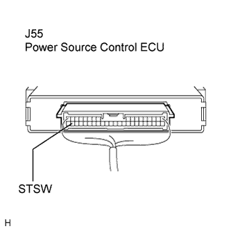
| 5.CHECK WIRE HARNESS (POWER SOURCE CONTROL ECU - ECM) |
Disconnect the A49 ECM connector.
Measure the resistance according to the value(s) in the table below.
- Standard resistance:
| Tester Connection (Symbols) | Condition | Specified Condition |
| J55-39 (STSW) - A49-9 (STSW) | Always | Below 1 Ω |
| J55-39 (STSW) or A49-9 (STSW) - Body ground | Always | 10 kΩ or higher |
Reconnect the A49 ECM connector.
Measure the voltage according to the value(s) in the table below.
- Standard voltage:
| Tester Connection (Symbols) | Condition | Specified Condition |
| J55-39 (STSW) - Body ground | Always | Below 1 V |
| | REPAIR OR REPLACE HARNESS OR CONNECTOR |
|
|
| 6.CHECK WIRE HARNESS (STEERING LOCK ECU - POWER SOURCE CONTROL ECU AND BODY GROUND) |
Disconnect the J29 ECU connector.
Measure the resistance according to the value(s) in the table below.
- Standard resistance:
| Tester Connection (Symbols) | Condition | Specified Condition |
| J29-1 (GND) - Body ground | Always | Below 1 Ω |
| J29-4 (SLP1) - J55-26 (SLP) | Always | Below 1 Ω |
| J29-4 (SLP1) or J55-26 (SLP) - Body ground | Always | 10 kΩ or higher |
| | REPAIR OR REPLACE HARNESS OR CONNECTOR |
|
|
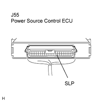
| 7.INSPECT POWER SOURCE CONTROL ECU |
Reconnect the J55 ECU connector.
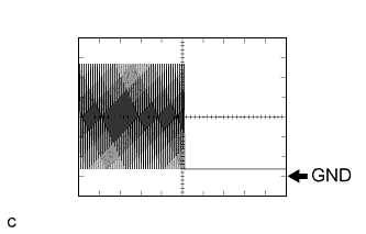
Connect the oscilloscope to the power source control ECU terminals specified in the table below and check the waveform.
| Item | Contents |
| Terminal (Symbols) | J55-26 (SLP) - Body ground |
| Equipment Setting | 2 V/DIV., 100 ms./DIV. |
| Condition | Engine switch on (IG) |
- OK:
- The waveform appears as shown in the illustration.
| | REPLACE POWER SOURCE CONTROL ECU |
|
|
| 8.INSPECT STEERING LOCK ECU |
Reconnect the J29 ECU connector.
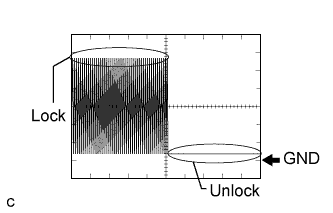
Connect the oscilloscope to the power source control ECU terminals specified in the table below and check the waveform.
| Item | Contents |
| Terminal (Symbols) | J55-26 (SLP) - Body ground |
| Equipment Setting | 2 V/DIV., 100 ms./DIV. |
| Condition | Steering is LOCK / UNLOCK |
- OK:
- The waveform appears as shown in the illustration.
| | REPLACE STEERING LOCK ECU |
|
|
| 9.INSPECT POWER SOURCE CONTROL ECU |
Disconnect the A49 ECM connector.
Measure the voltage according to the value(s) in the table below.
- Standard voltage:
| Tester Connection (Symbols) | Condition | Specified Condition |
| J55-39 (STSW) - Body ground | Clutch pedal depressed, Engine switch off (Released) | Below 1 V |
| Clutch pedal depressed, Engine switch on (IG) (hold on) | Output voltage at terminal AM2 is -2 V or more. |
| | REPLACE POWER SOURCE CONTROL ECU |
|
|