Lexus IS250 IS220d GSE20 ALE20 2AD-FHV LUBRICATION
ENGINE OIL COOLER - REMOVAL
| 1. DISCONNECT CABLE FROM NEGATIVE BATTERY TERMINAL |
| 2. REMOVE NO. 1 ENGINE COVER |
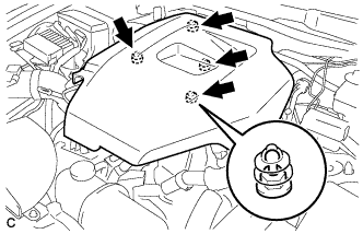
Remove the No. 1 engine cover.
| 3. REMOVE NO. 1 INLET AIR CLEANER |
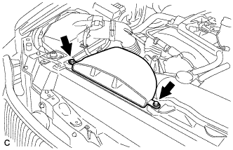
Remove the bolt, clip and inlet air cleaner.
| 4. REMOVE ENGINE ROOM SIDE COVER LH |
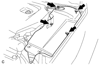
Remove the 4 clips and side cover.
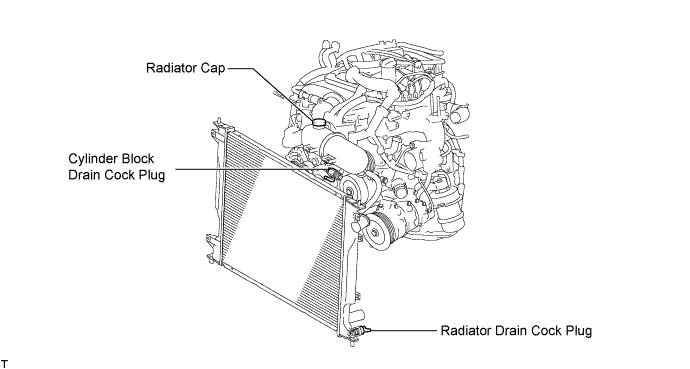
| 5. DRAIN ENGINE COOLANT |
- CAUTION:
- Do not remove the radiator cap while the engine and radiator are still hot. Pressurized, hot engine coolant and steam may be released and cause serious burns.
Remove the radiator cap.
Loosen the radiator drain cock plug and cylinder block drain cock plug. Then drain the coolant.
- HINT:
- Collect the coolant in a container and dispose of it according to local regulations.
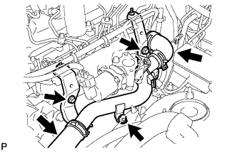
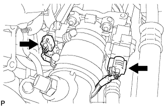
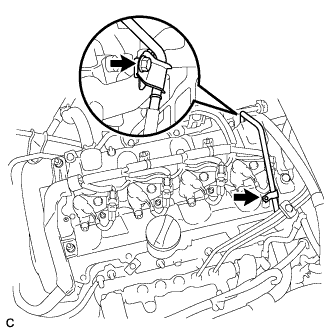
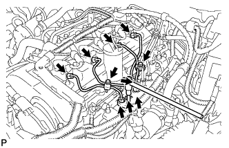
| 6. REMOVE WIRE HARNESS CLAMP BRACKET |
Disconnect the wiring harness clamp.
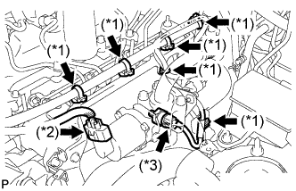
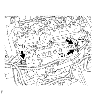
Disconnect the 6 wire harness clamps (*1).
Disconnect the EGR valve connector (*2).
Disconnect the oil pressure switch assembly connector (*3).
Remove the 2 bolts and wire harness clamp bracket.
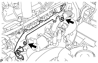
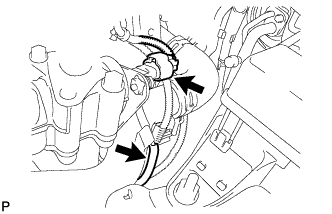
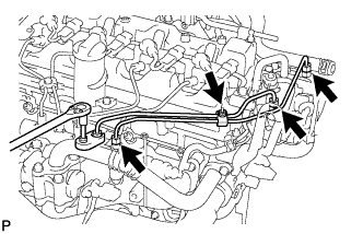
| 7. REMOVE NO. 2 EGR PIPE SUB-ASSEMBLY |
Remove the 2 nuts, 2 bolts and No. 2 EGR pipe.
| 8. REMOVE EGR VALVE ASSEMBLY |
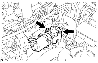
Remove the 2 bolts, EGR valve assembly and gasket.
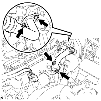
| 9. REMOVE NO. 1 WATER OUTLET PIPE |
Disconnect the manifold absolute pressure sensor connector and vacuum hose.
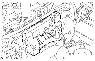
Remove the insulator.
Disconnect the 2 water hoses.
Remove the 3 bolts and No. 1 water outlet pipe.
| 10. REMOVE AIR PIPE SUB-ASSEMBLY |
Disconnect the 2 diesel throttle body connectors.
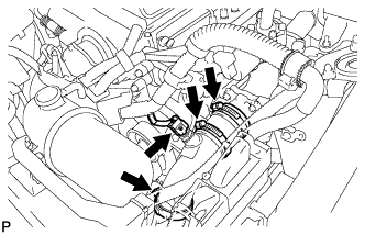
Loosen the 3 hose bands.
Disconnect the intake air temperature sensor connector.
Remove the bolt and air pipe sub-assembly.
Disconnect the wire harness clamp.
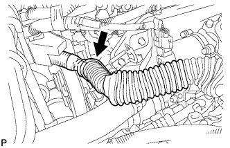
| 11. REMOVE NO. 4 AIR HOSE |
| 12. REMOVE DIESEL THROTTLE BODY |
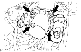
Remove the 2 nuts and 2 bolts, and then remove the diesel throttle body and gasket.
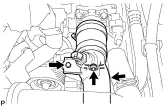
| 13. REMOVE NO. 1 FUEL PIPE |
Loosen the 2 clips and disconnect the 2 fuel hoses.
Remove the 2 bolts and the No. 1 fuel pipe.
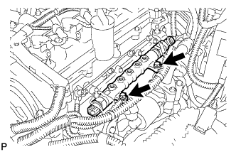
| 14. REMOVE NO. 1 INJECTION PIPE SUB-ASSEMBLY |
- NOTICE:
- After removing the fuel pipe, cover the common rail with electrical tape to prevent dirt or foreign objects from entering the pipe inlet. Also protect the injector inlets with electrical tape or plastic bags.
Remove the 2 bolts and 4 injection pipe clamps.
Using the SST, loosen the nut at the common rail end of the injection pipe.
- SST
- 09023-38401
Using the SST, loosen the nut at the injector end of the injection pipe.
- SST
- 09023-38401
Remove the No. 1 injection pipe sub-assembly.
| 15. REMOVE NO. 2 INJECTION PIPE SUB-ASSEMBLY |
- HINT:
- Perform the same procedure as for the No. 1 injection pipe.
| 16. REMOVE NO. 3 INJECTION PIPE SUB-ASSEMBLY |
- HINT:
- Perform the same procedure as for the No. 1 injection pipe.
| 17. REMOVE NO. 4 INJECTION PIPE SUB-ASSEMBLY |
- HINT:
- Perform the same procedure as for the No. 1 injection pipe.
| 18. REMOVE INLET FUEL PIPE SUB-ASSEMBLY |
Remove the bolt and 2 injection pipe clamps.
Using the SST, loosen the nut at the common rail end of the fuel inlet pipe.
- SST
- 09023-38401
Using the SST, loosen the nut at the supply pump end of the fuel inlet pipe.
- SST
- 09023-38401
Remove the 2 fuel inlet pipe sub-assemblies.
| 19. REMOVE COMMON RAIL ASSEMBLY |
Disconnect the fuel pressure sensor connector (*1).
Disconnect the fuel hose.
Disconnect the pressure discharge valve connector (*2).
Remove the 2 bolts and the common rail assembly.
| 20. REMOVE INTAKE MANIFOLD STAY |
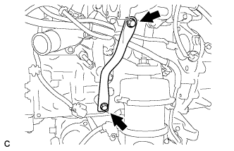
Remove the 2 bolts and intake manifold stay.
| 21. REMOVE INTAKE MANIFOLD SUB-ASSEMBLY |
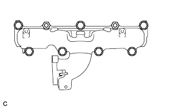
Remove the 7 bolts, 2 nuts and intake manifold sub-assembly.
Remove the intake manifold gasket from the cylinder head.
| 22. REMOVE OIL COOLER ASSEMBLY |
Loosen the clip and disconnect the water by-pass hose.
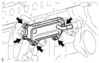
Remove the 5 bolts and oil cooler assembly.
Remove the 3 O-rings from the No. 1 oil cooler bracket.
| 23. REMOVE NO. 1 TURBO OIL PIPE |
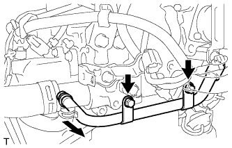
Remove the 2 bolts and No. 3 water by-pass pipe.
Remove the O-ring from the No. 3 water by-pass pipe.
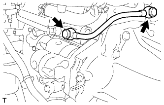
Remove the 2 union bolts, 2 gaskets and No. 1 turbo oil pipe.
| 24. REMOVE NO. 1 OIL COOLER BRACKET |
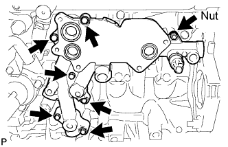
Remove the 6 bolts, nut and No. 1 oil cooler bracket.
Remove the 3 O-rings from the No. 1 oil cooler bracket.
| 25. REMOVE ENGINE OIL PRESSURE SWITCH ASSEMBLY |
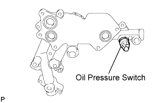
Remove the oil pressure switch assembly from the No. 1 oil cooler bracket.