Lexus IS250 IS220d GSE20 ALE20 2AD-FHV INTAKE
TURBOCHARGER - INSTALLATION
| 1. INSTALL STUD BOLT |
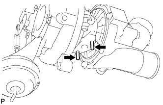
Install the 2 stud bolts (turbo oil outlet pipe side).
- Torque:
- 5.0 N*m{ 51 kgf*cm, 44 in.*lbf}
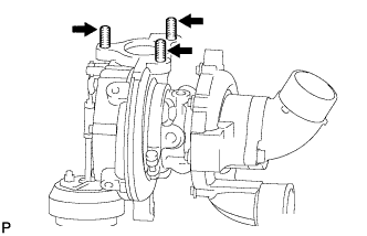
Install the 3 stud bolts (exhaust manifold side).
- Torque:
- 20 N*m{ 204 kgf*cm, 15 ft.*lbf}
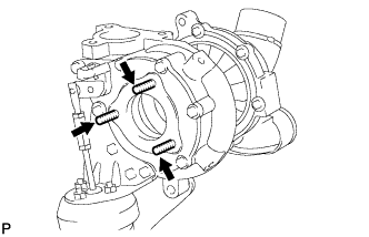
Install the 3 stud bolts (exhaust manifold convertor side).
- Torque:
- 10 N*m{ 102 kgf*cm, 7 ft.*lbf}
| 2. INSTALL TURBO OIL OUTLET PIPE |
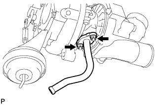
Install a new gasket and the turbo oil outlet pipe with the 2 nuts.
- Torque:
- 11 N*m{ 112 kgf*cm, 8 ft.*lbf}
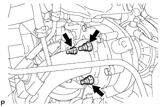
| 3. INSTALL WATER PIPE |
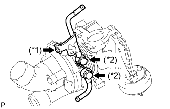
Temporarily install 2 new gaskets, No. 1 turbo water pipe sub-assembly and No. 2 turbo water pipe sub-assembly with the 2 union bolts and bolt.
Tighten the 2 union bolts (*2).
- Torque:
- 38 N*m{ 388 kgf*cm, 28 ft.*lbf}
Tighten the bolt (*1).
- Torque:
- 28 N*m{ 286 kgf*cm, 21 ft.*lbf}
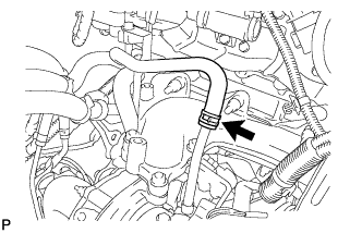
| 4. INSTALL TURBOCHARGER SUB-ASSEMBLY |
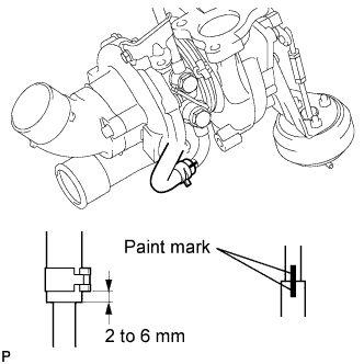
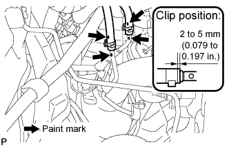
Install the No. 1 turbo water hose to the turbocharger sub-assembly.
- HINT:
- Install the clip an line up the paint marks as shown in the illustration.
Install the No. 1 turbo water hose to the No. 1 turbo water pipe.
Install a new gasket and turbocharger sub-assembly with the 3 nuts.
- Torque:
- 60 N*m{ 612 kgf*cm, 44 ft.*lbf}
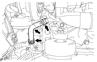
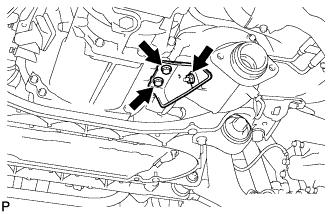
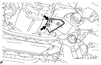
| 5. INSTALL NO. 2 TURBO OIL PIPE |
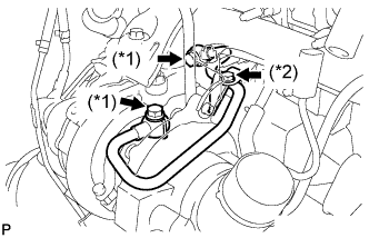
Temporarily install 2 new gaskets and No. 2 turbo oil pipe with the 2 union bolts and bolt.
Tighten the 2 union bolts (*1).
- Torque:
- 35 N*m{ 357 kgf*cm, 26 ft.*lbf}
Tighten the bolt (*2).
- Torque:
- 18 N*m{ 184 kgf*cm, 13 ft.*lbf}
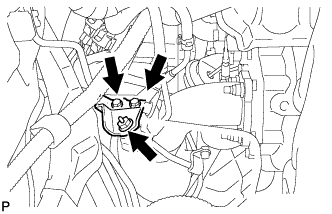
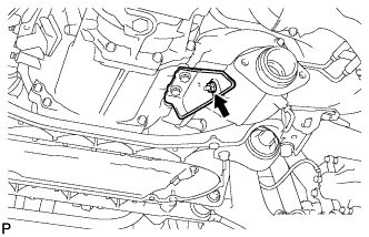
| 6. INSTALL TURBO OIL OUTLET HOSE |
Using pliers, slide the clip to install the turbo oil outlet hose.
| 7. INSTALL NO. 3 WATER BY-PASS HOSE |
Connect the No. 3 water by-pass hose.
| 8. INSTALL NO. 1 TURBO INSULATOR |
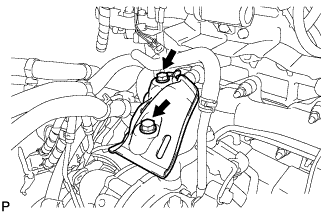
Install the insulator with the 2 bolts.
- Torque:
- 25 N*m{ 255 kgf*cm, 18 ft.*lbf}
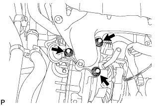
| 9. INSTALL TURBOCHARGER STAY |
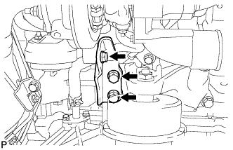
Install the turbocharger stay with the 3 bolts.
- Torque:
- 56 N*m{ 571 kgf*cm, 41 ft.*lbf}
| 10. INSTALL EXHAUST MANIFOLD CONVERTER SUB-ASSEMBLY |
Temporarily install the No. 1 manifold stay.
Temporarily install a new turbine outlet elbow gasket and exhaust manifold converter with the 3 nuts.
Temporarily install the 2 bolts and nut.
Tighten the 3 nuts (Pushing the manifold converter against the No. 1 manifold stay).
- Torque:
- 25 N*m{ 255 kgf*cm, 18 ft.*lbf}
Tighten the 2 bolts and nut.
- Torque:
- 56 N*m{ 571 kgf*cm, 41 ft.*lbf}
Temporarily install the No. 2 exhaust manifold stay with the 2 bolts and nut.
Tighten the 2 bolts (Pushing the No. 2 exhaust manifold stay against the manual transmission).
- Torque:
- 56 N*m{ 571 kgf*cm, 41 ft.*lbf}
Tighten the nut.
- Torque:
- 56 N*m{ 571 kgf*cm, 41 ft.*lbf}
Using pliers, slide the clip to install the No. 1 and No. 2 vacuum transmitting hose assembly.
- HINT:
- Make sure that the paint marks on the No. 1 and No. 2 vacuum transmitting hose assemblies and No. 1 and No. 2 vacuum pipes are aligned.
| 11. INSTALL FRONT EXHAUST PIPE ASSEMBLY |
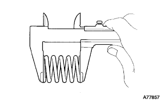
Using vernier calipers, measure the free length of the compression springs.
- Minimum length:
- 38.5 mm (1.516 in.)
If the free length is less than the minimum, replace the compression spring.
Fully insert 2 new gaskets to the exhaust manifold converter and front exhaust pipe assembly by hand.
- NOTICE:
- HINT:
- Using a plastic hammer, uniformly strike the gasket so that the gasket and front exhaust pipe are properly fit.
Install the front exhaust pipe assembly.
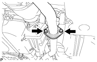
Install the 2 bolts and 2 compression springs.
- Torque:
- 43 N*m{ 439 kgf*cm, 32 ft.*lbf}
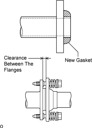
- NOTICE:
- After installation, check that the clearance is almost the same at any point between the flanges of the tail exhaust pipe assembly and front exhaust pipe assembly.
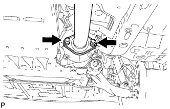
Install the 2 bolts and 2 compression springs.
- Torque:
- 43 N*m{ 439 kgf*cm, 32 ft.*lbf}
- NOTICE:
- After installation, check that the clearance is almost the same at any point between the flanges of the exhaust manifold converter and front exhaust pipe assembly.
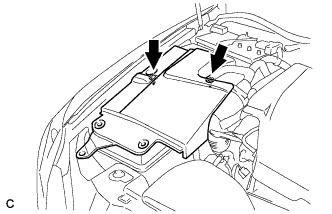
| 12. INSTALL BATTERY TRAY |
| 13. INSTALL POWER STEERING ECU ASSEMBLY |
- HINT:
| 14. INSTALL AIR HOSE |
| 15. INSTALL NO. 2 AIR HOSE |
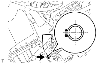
Install the No. 2 air hose to the intercooler and secure it with the clip.
- HINT:
- Make sure that the claws on the clip are positioned as shown in the illustration.
| 16. INSTALL NO. 1 AIR TUBE |
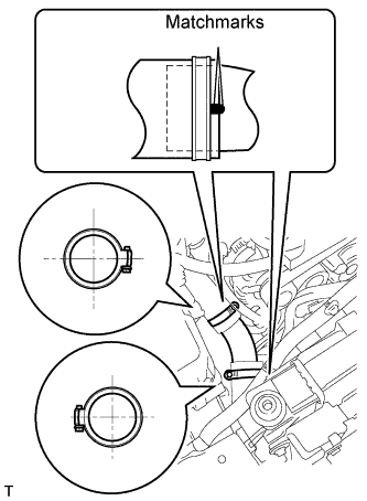
Align the matchmarks, install the No. 1 air tube to the intercooler and secure it with the 2 clips.
- HINT:
- Make sure that the claws on the 2 clips are positioned as shown in the illustration.
| 17. INSTALL AIR CLEANER CAP WITH AIR CLEANER HOSE |
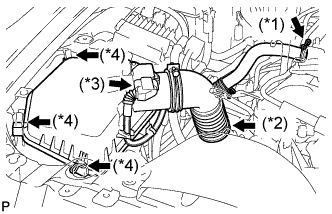
Install the air cleaner cap with air cleaner hose.
Connect the No. 2 ventilation hose (*1).
Connect the hose band (*2).
Connect the mass air flow meter connector (*3).
Connect the 3 clamps (*4).
| 18. CHECK FOR EXHAUST GAS LEAKS |
| 19. INSTALL ENGINE ROOM SIDE COVER RH |
Install the side cover with the 2 clips.
| 20. INSTALL COOL AIR INTAKE DUCT SEAL |

Install the intake duct seal with the 11 clips.
| 21. INSTALL NO. 1 ENGINE COVER |
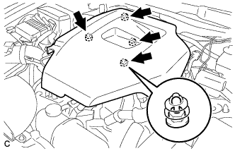
Install the No. 1 engine cover.