Lexus IS250 IS220d GSE20 ALE20 2AD-FHV FUEL
FUEL TANK - INSTALLATION
| 1. INSTALL NO. 2 FUEL TANK PROTECTOR |
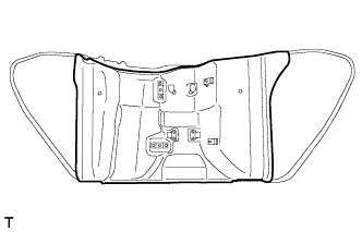
Install the No. 2 fuel tank protector to the fuel tank assembly.
| 2. INSTALL FUEL TANK CUSHION |
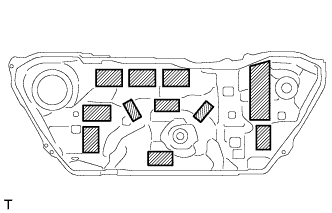
Install 11 new fuel tank cushions as shown in the illustration.
| 3. INSTALL FUEL TANK TO FILLER PIPE HOSE |
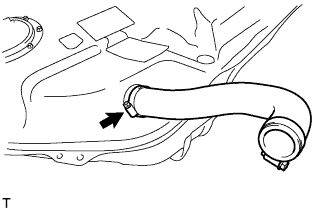
Install the fuel tank to filler pipe hose to the fuel tank with the clamp.
Tighten the hose clamp bolt.
| 4. INSTALL FUEL TANK RETURN TUBE SUB-ASSEMBLY |
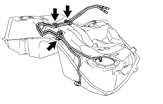
Install the 3 clamps to the fuel tank.
Install the fuel tank return tube sub-assembly with the 3 clamps.
| 5. INSTALL FUEL TANK MAIN TUBE SUB-ASSEMBLY |
Install the clamp to the fuel tank.
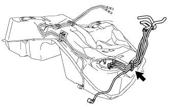
Install the fuel tank main tube sub-assembly with the clamp.
| 6. INSTALL FUEL TANK VENT HOSE |
Install the fuel tank vent hose with the clip.
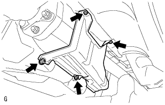
| 7. INSTALL NO. 1 FUEL TANK BREATHER TUBE SUB-ASSEMBLY |
Install a new gasket to the No. 1 fuel tank breather tube sub-assembly.
Install the No. 1 fuel tank breather tube sub-assembly with the 4 bolts.
- Torque:
- 1.5 N*m{ 15 kgf*cm, 13 in.*lbf}
| 8. INSTALL FUEL TANK ASSEMBLY |
Set the fuel tank assembly onto the transmission jack.
Raise the transmission jack so that the fuel tank breather hose can be connected. Connect the hose.
- NOTICE:
- Slowly raise the jack to prevent the fuel tank assembly from dropping.
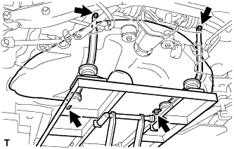
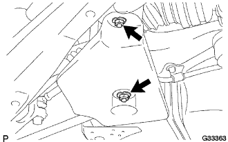
Install the fuel tank assembly with the fuel tank band and 4 bolts.
- Torque:
- 39 N*m{ 398 kgf*cm, 29 ft.*lbf}
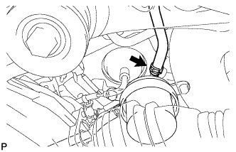
| 9. CONNECT FUEL TANK TO FILLER PIPE HOSE |
Connect the fuel tank to filler pipe hose with the clamp.
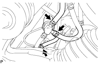
| 10. CONNECT FUEL TANK RETURN TUBE SUB-ASSEMBLY |
Connect the fuel tube clamp.
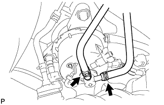
Connect the 2 fuel tubes to the fuel sedimenter assembly.
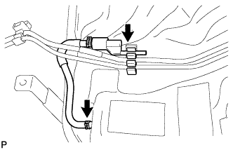
| 11. CONNECT FUEL TANK MAIN TUBE SUB-ASSEMBLY |
Connect the fuel tube to the fuel filter.
Connect the 3 fuel tubes to the fuel route switching valve.
| 12. CONNECT FUEL TUBE |
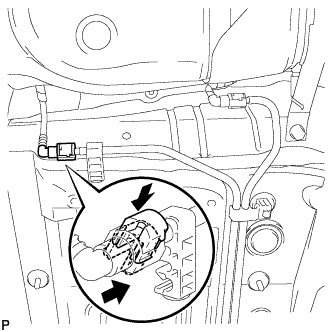
Connect the fuel tank main tube.
Push in the fuel tube connector to the pipe and push up the retainer to engage the claws.
- NOTICE:
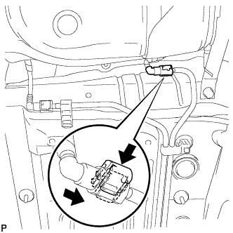
Connect the fuel tank return vent tube.
Push in the fuel tube connector to the pipe and push up the retainer to engage the claws.
- NOTICE:
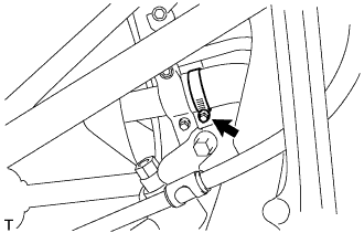
| 13. CONNECT PARKING BRAKE CABLE ASSEMBLY |
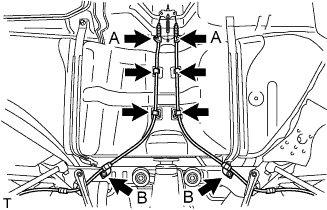
Connect the 4 clamps.
Connect the 2 parking brake cables with the 4 bolts.
- Torque:
- bolt A:
- 6.0 N*m{ 61 kgf*cm, 53 in.*lbf}
- bolt B:
- 19 N*m{ 194 kgf*cm, 14 ft.*lbf}
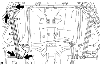
| 14. INSTALL REAR SUSPENSION MEMBER BRACE LH |
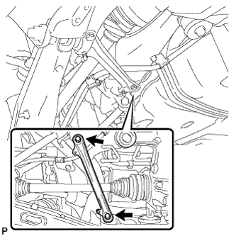
Install the rear suspension member brace LH with the 2 bolts.
- Torque:
- 50 N*m{ 510 kgf*cm, 37 ft.*lbf}
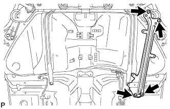
| 15. INSTALL REAR SUSPENSION MEMBER BRACE RH |
- HINT:
- Installation procedure of the RH side is the same as that of the LH side.
| 16. INSTALL PROPELLER SHAFT WITH CENTER BEARING ASSEMBLY |
- HINT:
- .
| 17. INSPECT AND ADJUST NO. 2 AND NO. 3 JOINT ANGLE |
Stabilize the propeller shaft and differential.
Turn the propeller shaft several times by hand to stabilize the center support bearing.
Check both the No. 2 and No. 3 joint angles.
Using SST, measure the installation angle of the intermediate shaft and propeller shaft.
- SST
- 09370-50010
- HINT:
- The SST should be set directly on the bottom of the shaft.
Using SST, measure the installation angle of the differential.
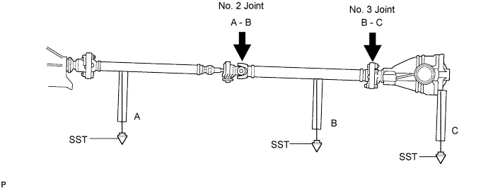
- SST
- 09370-50010
- HINT:
- Measure the installation angle by placing the SST in the positions shown in the illustration.
Calculate the No. 2 joint angle.
- No. 2 joint angle:
- A - B = -0°49' to -1°49'
- A:
- Intermediate shaft installation angle
- B:
- Propeller shaft installation angle
Calculate the No. 3 joint angle.
- No. 3 joint angle:
- B - C = 0°70' to 2°10'
- B:
- Propeller shaft installation angle
- C:
- Differential installation angle
- HINT:
- If the measured angle is not within the specified range, adjust it with the center support bearing washers.
Adjust the No. 2 joint angle.
Select the center support bearing washers for adjustment.
| thickness mm (in.) |
| 2 (0.0787) |
| 4.5 (0.1772) |
| 6.5 (0.2559) |
| 9.0 (0.3543) |
| 11.0 (0.4331) |
- NOTICE:
- The 2 washers should be the same thickness.
| 18. INSTALL NO. 1 FRONT FLOOR HEAT INSULATOR |
Install the front No. 1 floor heat insulator with the 4 nuts.
- Torque:
- 5.4 N*m{ 55 kgf*cm, 48 in.*lbf}
| 19. INSTALL AIR GUIDE PLATE OUTSIDE RH |
Install the outside air guide plate RH with the 4 nuts.
- Torque:
- 5.4 N*m{ 55 kgf*cm, 48 in.*lbf}
| 20. INSTALL FRONT EXHAUST PIPE ASSEMBLY |
- HINT:
- .
| 21. INSTALL AIR FUEL RATIO SENSOR |
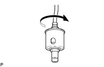
Before installing the air fuel ratio sensor, twist the sensor wire counterclockwise 4 turns.
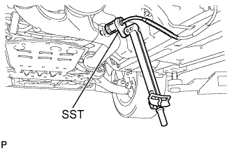
Using SST, install the air fuel ratio sensor to the front exhaust pipe.
- SST
- 09224-00010
- Torque:
- 44 N*m{ 449 kgf*cm, 33 ft.*lbf}
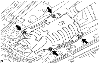
| 22. INSTALL FRONT CENTER FLOOR BRACE |
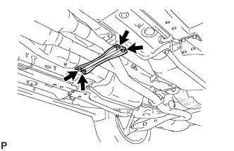
Install the front center floor brace with the 4 bolts.
- Torque:
- 7.4 N*m{ 75 kgf*cm, 65 in.*lbf}
| 23. INSTALL REAR SUSPENSION MEMBER BRACE LOWER LH |
Install the suspension member brace lower LH with the 4 bolts.
- Torque:
- 19 N*m{ 195 kgf*cm, 14 ft.*lbf}
| 24. INSTALL REAR SUSPENSION MEMBER BRACE LOWER RH |
Install the suspension member brace lower RH with the 4 bolts.
- Torque:
- 19 N*m{ 195 kgf*cm, 14 ft.*lbf}
| 25. INSTALL REAR NO. 1 FLOOR PANEL BRACE |
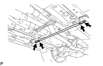
Install the rear No. 1 floor panel brace with the 4 bolts.
- Torque:
- 19 N*m{ 195 kgf*cm, 14 ft.*lbf}
| 26. INSTALL FLOOR UNDER COVER |
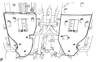
Install the No. 1 floor under cover and No. 2 floor under cover.
| 27. INSTALL NO. 2 DIFFERENTIAL SUPPORT PROTECTOR |
Install the No. 2 differential support protector to the rear suspension member brace with the 2 nuts.
- Torque:
- 5.4 N*m{ 55 kgf*cm, 48 in.*lbf}
| 28. INSTALL NO. 1 DIFFERENTIAL SUPPORT PROTECTOR |
- HINT:
- Installation procedure of the No. 1 differential support protector is the same as that of the No. 2 differential support protector.
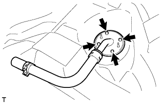
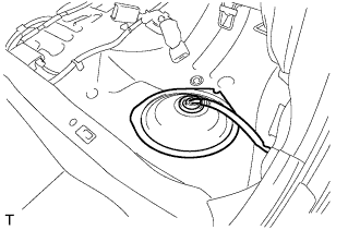
| 29. INSTALL FUEL SENDER GAUGE ASSEMBLY |
Install the fuel sender gauge to the fuel tank with the 5 bolts.
- Torque:
- 1.5 N*m{ 15 kgf*cm, 13 in.*lbf}
Connect the fuel sender gauge connector.
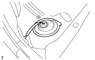
| 30. INSTALL FUEL SUCTION WITH PUMP AND GAUGE TUBE ASSEMBLY |
Install a new gasket onto the fuel tank.
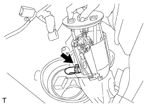
Connect the fuel hose with the clip.
Set the fuel suction tube to the fuel tank.
- NOTICE:
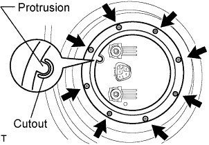
Align the protrusion of the fuel suction tube and the cutout of the fuel tank vent tube set plate.
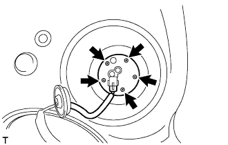
While holding the fuel suction tube by hand, install the fuel tank vent tube to the fuel tank with the 8 bolts.
- Torque:
- 6.0 N*m{ 61 kgf*cm, 53 in.*lbf}
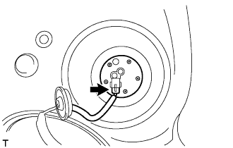
Connect the fuel tube.
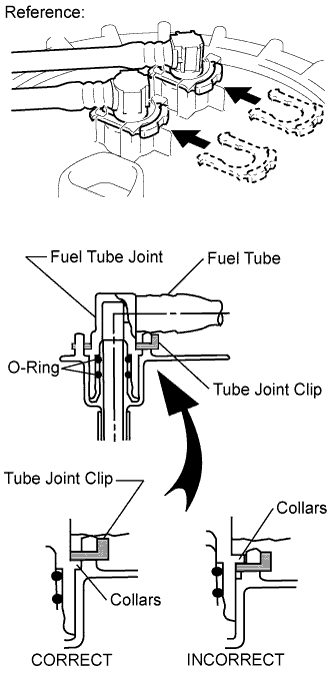
Push the fuel tube joint in the plug of the fuel suction plate, then install the 2 tube joint clips.
- NOTICE:
Connect the fuel suction tube connector.
| 31. INSPECT PARKING BRAKE LEVER TRAVEL |
Pull firmly on the parking brake lever.
Release the parking brake lock, and return the parking brake lever to its off position.
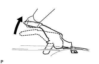
Slowly pull the parking brake lever all the way up, and count the number of clicks.
- Parking brake lever travel:
- 4 to 6 notches at 200 N (20 kgf, 45 lbf)
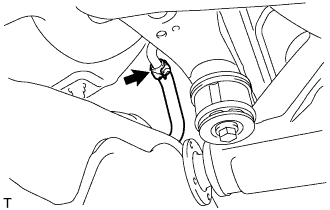
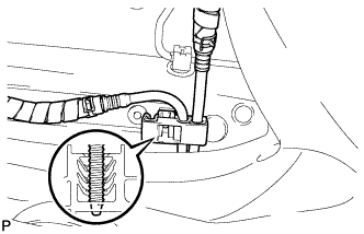
| 32. ADJUST PARKING BRAKE LEVER TRAVEL |
Depress the parking brake lever. Hold the No. 1 wire adjusting nut using a wrench and loosen the lock nut.
Release the parking brake lever.
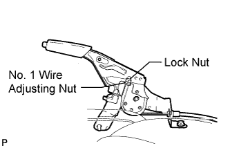
Turn the No. 1 wire adjusting nut until the parking brake lever travel meets the above specification.
Hold the No. 1 wire adjusting nut using a wrench or equivalent tool and tighten the lock nut.
- Torque:
- 6.0 N*m{ 61 kgf*cm, 53 in.*lbf}
Count the number of clicks after depressing and releasing the parking brake lever 3 or 4 times.
Check whether the parking brake drags or not.
When operating the parking brake lever, check that the parking brake indicator light comes on.
| 33. ADD FUEL |
| 34. CONNECT CABLE TO NEGATIVE BATTERY TERMINAL |
- Torque:
- 5.4 N*m{ 55 kgf*cm, 48 in.*lbf}
| 35. CHECK FOR FUEL LEAKS |
PERFORM ACTIVE TEST
Connect the intelligent tester to the DLC3.
Turn the engine switch ON (IG).
Turn the intelligent tester ON.
Enter the following menus: Powertrain / ENGINE / Active Test.
Perform the Active Test.
| Intelligent Tester Display | Test Details | Control Range | Diagnostic Notes |
| Test the Fuel Leak | Pressurize common rail internal fuel pressure, and check for fuel leaks | Stop/Start | Fuel pressure inside common rail pressurized to specified value and engine speed increased to 2,000 rpm when "Start" is selected Above conditions to be maintained while "Start" is selected |
| 36. CHECK FOR EXHAUST GAS LEAKAGE |
| 37. INSTALL REAR FLOOR SERVICE HOLE COVER |
Install the service hole cover with new butyl tape.
| 38. INSTALL REAR NO. 2 FLOOR SERVICE HOLE COVER |
Install the rear No. 2 floor service hole cover with new butyl tape.
| 39. INSTALL REAR SEAT CUSHION ASSEMBLY |
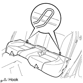
Attach the 2 rear hooks of the seat cushion to the seatback.
Attach the 2 front hooks of the seat cushion to the vehicle body.
Confirm that the seat cushion is firmly installed.
- NOTICE:
- When installing the seat cushion, make sure the seat belt buckle is not under the seat cushion.
| 40. PERFORM INITIALIZATION |
Perform initialization procedure .
- HINT:
- Some vehicle systems require initialization after reconnecting the negative battery terminal.