Lexus IS250 IS220d GSE20 ALE20 2AD-FHV FUEL
FUEL INJECTOR - INSTALLATION
| 1. INSTALL INJECTOR ASSEMBLY |
Install 4 new nozzle seats to the cylinder head.
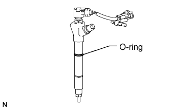
Install new O-rings to each injector.
Apply a light coat of engine oil to the O-rings on each injector.
Install the 4 injectors to the cylinder head.
- NOTICE:
- Fit the injectors to the nozzle seats.
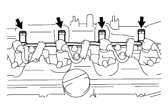
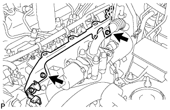
| 2. INSTALL NOZZLE HOLDER CLAMP |
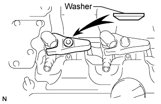
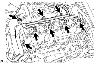
Install the nozzle holder clamps and washers as shown in the illustration.
Temporarily install the nozzle holder clamp bolts.
- NOTICE:
- HINT:
- Apply a light coat of engine oil to the threads of the nozzle holder clamp bolts.
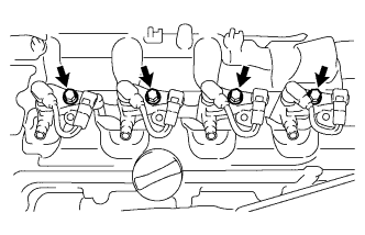
Temporarily install the 4 clamps to the cylinder head with the 4 bolts.
Using a hexagon socket wrench, tighten the 4 bolts.
- Torque:
- 9.0 N*m{ 92 kgf*cm, 80 in.*lbf}
Temporarily install the No. 1, No. 2, No. 3 and No. 4 injection pipes.
Temporarily install 4 new gaskets, and No. 1 leakage pipe with the 4 union bolts.
Tighten the 4 nozzle holder clamp bolts.
- Torque:
- 25 N*m{ 255 kgf*cm, 18 ft.*lbf}
Remove the No. 1, No. 2, No. 3 and No. 4 injection pipes.
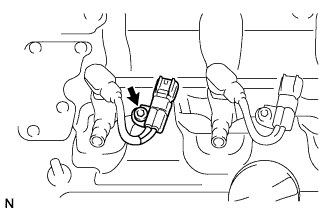
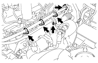
| 3. INSTALL NO. 1 NOZZLE LEAKAGE PIPE ASSEMBLY |
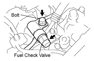
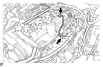
Temporarily install a new gasket, fuel check valve and bolt.
Tighten the 4 union bolts.
- Torque:
- 18 N*m{ 184 kgf*cm, 13 ft.*lbf}
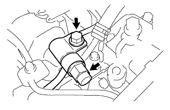
Tighten the fuel check valve and bolt.
- Torque:
- For fuel check valve:
- 32 N*m{ 321 kgf*cm, 23 ft.*lbf}
- For bolt:
- 21 N*m{ 214 kgf*cm, 15 ft.*lbf}
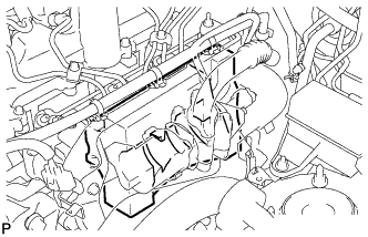
| 4. INSTALL FUEL INLET PIPE SUB-ASSEMBLY |
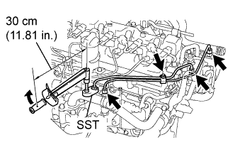
Temporarily install the 2 fuel inlet pipes, 2 injection pipe clamps and the bolt.
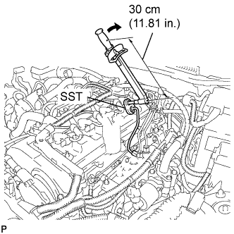
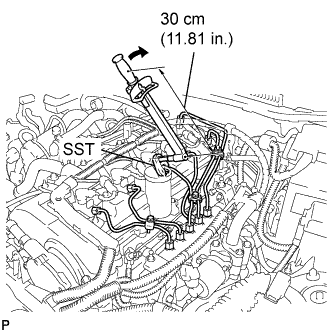
Using the SST, first tighten the nut at the common rail end of the fuel inlet pipe.
- SST
- 09023-38401
- Torque:
- 27 N*m{ 275 kgf*cm, 20 ft.*lbf}
- HINT:
If the pipe is deformed or twisted, or if it cannot be installed properly, replace the pipe with a new one.
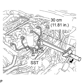
Using the SST, tighten the nut at the fuel supply pump of the fuel inlet pipe.
- SST
- 09023-38401
- Torque:
- 27 N*m{ 275 kgf*cm, 20 ft.*lbf}
- HINT:
If the pipe is deformed or twisted, or if it cannot be installed properly, replace the pipe with a new one.
Tighten the 2 injection pipe clamps with the bolt.
- Torque:
- 5.0 N*m{ 51 kgf*cm, 44 in.*lbf}
| 5. CONNECT ENGINE WIRE |
Install the engine wire harness to the cylinder head cover.
Connect the 2 harness clamps and the 4 injector connectors.
Install the 2 nuts.
- Torque:
- 2.2 N*m{ 22 kgf*cm, 19 in.*lbf}
| 6. INSTALL NO. 4 INJECTION PIPE SUB-ASSEMBLY |
- NOTICE:
- In cases where an injector is replaced, the injection pipes must also be replaced.
Temporarily install the injection pipe.
Using the SST, first tighten the nut at the common rail end of the injection pipe.
- SST
- 09023-38401
- Torque:
- 27 N*m{ 275 kgf*cm, 20 ft.*lbf}
- HINT:
If the pipe is deformed or twisted, or if it cannot be installed properly, replace the pipe with a new one.
Using the SST, tighten the nut at the injector end of the injection pipe.
- SST
- 09023-38401
- Torque:
- 27 N*m{ 275 kgf*cm, 20 ft.*lbf}
- HINT:
If the pipe is deformed or twisted, or if it cannot be installed properly, replace the pipe with a new one.
| 7. INSTALL NO. 3 INJECTION PIPE SUB-ASSEMBLY |
- NOTICE:
- In cases where an injector is replaced, the injection pipes must also be replaced.
Temporarily install the 3 injection pipes and the 4 injection pipe clamps with the 2 bolts.
Using the SST, first tighten the nut at the common rail end of the injection pipe.
- SST
- 09023-38401
- Torque:
- 27 N*m{ 275 kgf*cm, 20 ft.*lbf}
- HINT:
If the pipe is deformed or twisted, or if it cannot be installed properly, replace the pipe with a new one.
Using the SST, tighten the nut at the injector end of the injection pipe.
- SST
- 09023-38401
- Torque:
- 27 N*m{ 275 kgf*cm, 20 ft.*lbf}
- HINT:
If the pipe is deformed or twisted, or if it cannot be installed properly, replace the pipe with a new one.
| 8. INSTALL NO. 2 INJECTION PIPE SUB-ASSEMBLY |
- HINT:
- Perform the same procedure as for the No. 3 injection pipe.
| 9. INSTALL NO. 1 INJECTION PIPE SUB-ASSEMBLY |
- HINT:
- Perform the same procedure as for the No. 3 injection pipe.
Tighten the 4 injection pipe clamps with the 2 bolts.
- Torque:
- 5.0 N*m{ 51 kgf*cm, 44 in.*lbf}
| 10. INSTALL NO. 1 INTAKE MANIFOLD INSULATOR |
Install the No. 1 intake manifold insulator.
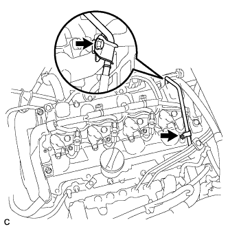
| 11. INSTALL WIRING HARNESS CLAMP BRACKET |
Install the wire harness clamp bracket with the 2 bolts.
Connect the 5 wire harness clamps.
Connect the wire harness clamp.
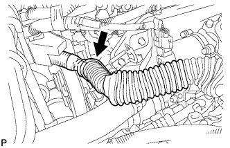
| 12. INSTALL NO. 1 FUEL PIPE |
Install the No. 1 fuel pipe with the 2 bolts.
Connect the 2 fuel hoses and 2 clips.
| 13. CONNECT CABLE TO NEGATIVE BATTERY TERMINAL |
| 14. REGISTER INJECTOR COMPENSATION CODE |
- HINT:
- Each injector assembly has a characteristic fuel injecting behavior .
| 15. CHECK FOR FUEL LEAKS |
PERFORM ACTIVE TEST
Connect the intelligent tester to the DLC3.
Turn the engine switch ON (IG).
Turn the intelligent tester ON.
Enter the following menus: Powertrain / ENGINE / Active Test.
Perform the Active Test.
| Intelligent Tester Display | Test Details | Control Range | Diagnostic Notes |
| Test the Fuel Leak | Pressurize common rail internal fuel pressure, and check for fuel leaks | Stop/Start | Fuel pressure inside common rail pressurized to specified value and engine speed increased to 2,000 rpm when "Start" is selected Above conditions to be maintained while "Start" is selected |
| 16. INSTALL NO. 1 ENGINE COVER |
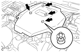
Install the No. 1 engine cover.
| 17. PERFORM INITIALIZATION |
Perform initialization procedure .
- HINT:
- Some vehicle systems require initialization after reconnecting the negative battery terminal.