Lexus IS250 IS220d GSE20 ALE20 2AD-FHV FUEL
FUEL FILTER - REPLACEMENT
- HINT:
- When replacing the filter, use TOYOTA genuine parts or equivalent parts.
| 1. DISCONNECT CABLE FROM NEGATIVE BATTERY TERMINAL |
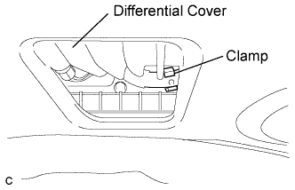
| 2. REMOVE NO. 2 DIFFERENTIAL SUPPORT PROTECTOR |
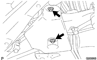
Remove the 2 nuts and No. 2 differential support protector from the suspension member brace.
| 3. REMOVE NO. 1 DIFFERENTIAL SUPPORT PROTECTOR |
- HINT:
- Removal procedure of the No. 1 differential support protector is the same as that of the No. 2 differential support protector.
| 4. REMOVE REAR SUSPENSION MEMBER BRACE LH |
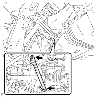
Remove the 2 bolts and rear suspension member brace LH.
| 5. REMOVE REAR SUSPENSION MEMBER BRACE RH |
- HINT:
- Removal procedure of the RH side is the same as that of the LH side.
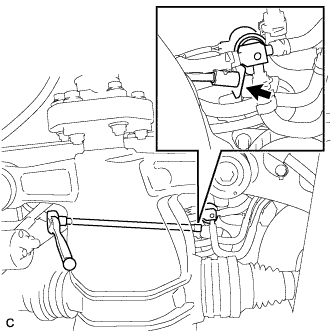
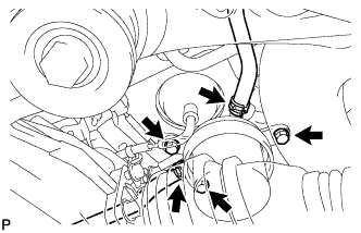
| 6. SEPARATE FUEL SEDIMENTER ASSEMBLY |
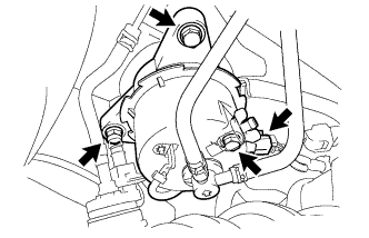
Remove the 3 bolts and disconnect the fuel sedimenter connector.
Separate the fuel sedimenter assembly from the fuel sedimenter support.
Loosen the upper drain bolt.
- NOTICE:
- Do not tilt the fuel sedimenter excessively.
Install a suitable vinyl tube onto the lower drain bolt.
Loosen the drain bolt, and drain the fuel from the fuel sedimenter, then drain the fuel into a container.
| 7. LOOSEN FUEL TANK CAP ASSEMBLY |
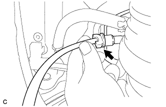
| 8. SEPARATE FUEL ROUTE SWITCHING VALVE ASSEMBLY |
Separate the fuel hose from the fuel tube clamp.
Remove the bolt and separate the fuel route switching valve.
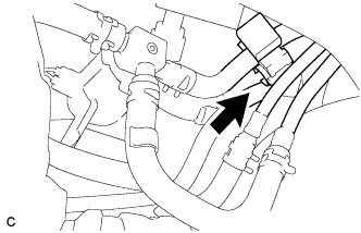
Separate the 3 fuel hoses from the No. 2 fuel tube clamp.
| 9. REMOVE FUEL FILTER ASSEMBLY |
Disconnect the 2 fuel hoses and remove the 3 bolts.
- NOTICE:
- Plug the filter and hoses immediately after disconnecting the hoses.
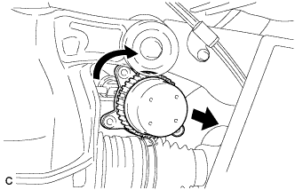
Remove the fuel filter assembly.
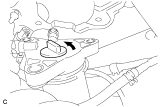
- HINT:
- Turn the filter clockwise to find a position that allows it to be removed.
| 10. REMOVE FUEL FILTER ELEMENT |
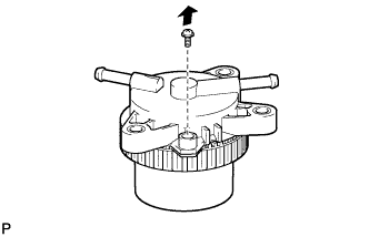
Remove the screw.
Loosen the fastener nut until it can be loosened by hand.
- NOTICE:
- Be careful not to damage the fuel filter.
Fully loosen the fastener nut by hand.
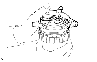
To remove the cap, pull up one side of the cap and then lift it off.
- NOTICE:
- Be careful not to damage the fuel filter.
| 11. INSTALL FUEL FILTER ELEMENT |
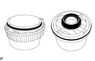
Attach 2 new O-rings to a new element and a new O-ring to the case.
Install the element to the case.
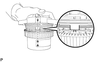
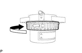
Align the marks on the cap and the case.
- NOTICE:
- Be careful not to damage the fuel filter.
Push the cap into the case by hand.
- Clearance (A):
- 1.5 mm (0.059 in.) or less
- HINT:
- The clearance between the cap and case should be even around the entire circumference of the cap and case.
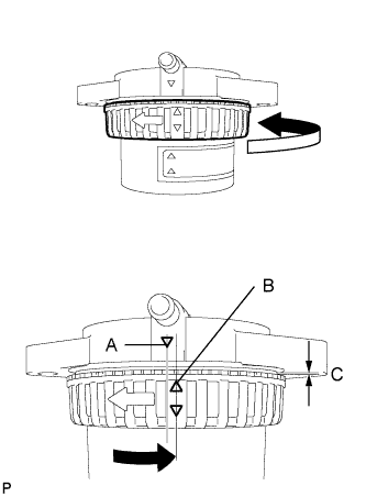
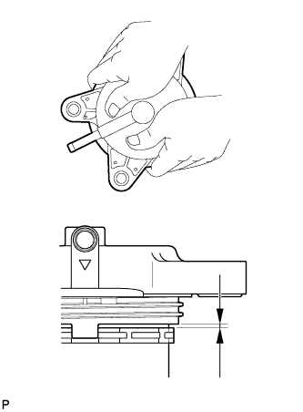
Tighten the fastener nut as shown in the illustration.
- HINT:
- Make sure that the fastener nut is tightened until mark B (on the fastener nut) goes beyond mark A (on the case) and that dimension C (clearance between the case and fastener nut) is 2 mm (0.079in.) or less.
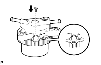
Install the screw to the cap.
| 12. INSTALL FUEL FILTER ASSEMBLY |
Install the fuel filter assembly with the 3 bolts.
- Torque:
- 29 N*m{ 296 kgf*cm, 21 ft.*lbf}
Connect the 2 fuel hoses with the clips.
| 13. INSTALL FUEL ROUTE SWITCHING VALVE ASSEMBLY |
Install the 3 fuel hoses to the No. 2 fuel tube clamp.
Install the fuel route switching valve with the bolt.
- Torque:
- 15 N*m{ 153 kgf*cm, 11 ft.*lbf}
Install the fuel hose to the clamp.
| 14. TIGHTEN FUEL TANK CAP ASSEMBLY |
| 15. INSTALL FUEL SEDIMENTER ASSEMBLY |
Tighten the 2 drain bolts.
Install the fuel sedimenter assembly to the fuel sedimenter support with the 3 bolts.
- Torque:
- 29 N*m{ 296 kgf*cm, 21 ft.*lbf}
Connect the fuel sedimenter connector.
| 16. INSTALL REAR SUSPENSION MEMBER BRACE LH |
Install the rear suspension member brace LH with the 2 bolts.
- Torque:
- 50 N*m{ 510 kgf*cm, 37 ft.*lbf}
| 17. INSTALL REAR SUSPENSION MEMBER BRACE RH |
- HINT:
- Installation procedure of the RH side is the same as that of the LH side.
| 18. INSTALL NO. 2 DIFFERENTIAL SUPPORT PROTECTOR |
Install the No. 2 differential support protector to the rear suspension member brace with the 2 nuts.
- Torque:
- 5.4 N*m{ 55 kgf*cm, 48 in.*lbf}
| 19. REMOVE NO. 1 DIFFERENTIAL SUPPORT PROTECTOR |
- HINT:
- Installation procedure of the No. 1 differential support protector is the same as that of the No. 2 differential support protector.
| 20. CONNECT CABLE TO NEGATIVE BATTERY TERMINAL |
| 21. PERFORM INITIALIZATION |
Perform initialization procedure .
- HINT:
- Some vehicle systems require initialization after reconnecting the negative battery terminal.