Lexus IS250 IS220d GSE20 ALE20 2AD-FHV ENGINE MECHANICAL
ENGINE ASSEMBLY - INSTALLATION
| 1. INSTALL FUEL SUPPLY PUMP ASSEMBLY |
- HINT:
- .
| 2. INSTALL ENGINE OIL LEVEL SENSOR |
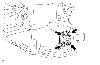
Install the engine oil level sensor and a new gasket with the 4 bolts.
- Torque:
- 7.0 N*m{ 71 kgf*cm, 62 in.*lbf}
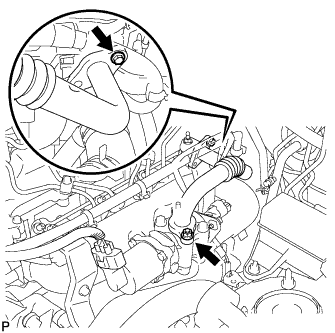
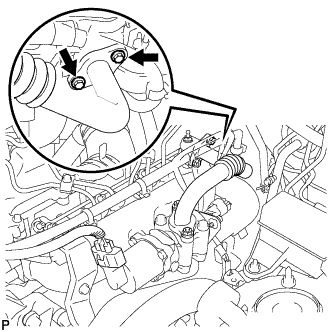
| 3. INSTALL WATER INLET HOUSING |
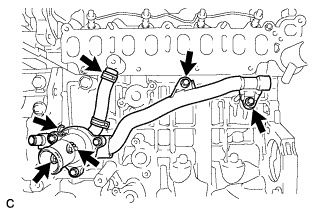
Install a new gasket and water inlet housing with the 3 nuts.
- Torque:
- 9.0 N*m{ 92 kgf*cm, 80 in.*lbf}
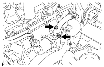
Connect the hose.
Install a new O-ring and No. 2 water by-pass pipe with the 2 bolts.
- Torque:
- 11 N*m{ 112 kgf*cm, 8 ft.*lbf}
| 4. INSTALL NO. 1 OIL COOLER BRACKET |
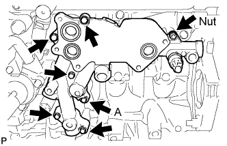
Install 3 new O-rings and oil cooler bracket with the 6 bolts and nut.
- Torque:
- 11 N*m{ 112 kgf*cm, 8 ft.*lbf}
- Bolt length:
Item Length Bolt A 36 mm (1.42 in.) Except bolt A 49 mm (1.93 in.)
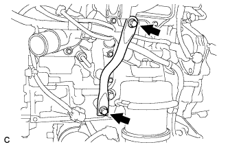
| 5. INSTALL NO. 1 TURBO OIL PIPE |
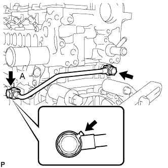
Install the No. 1 turbo oil pipe and 2 new gaskets with the 2 union bolts.
- Torque:
- 35 N*m{ 357 kgf*cm, 26 ft.*lbf}
- HINT:
- Be sure to install union bolt A so that the gasket is positioned as shown in the illustration.
| 6. INSTALL NO. 3 WATER BY-PASS PIPE |
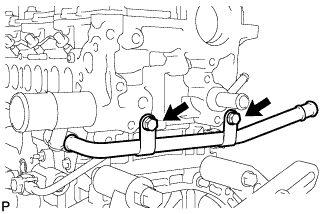
Install a new O-ring and No. 3 water by-pass pipe with the 2 bolts.
- Torque:
- 21 N*m{ 214 kgf*cm, 15 ft.*lbf}
| 7. INSTALL ENGINE COOLANT TEMPERATURE SENSOR |
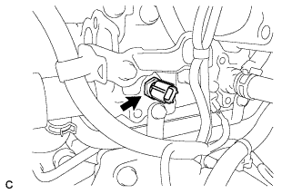
Install a new gasket and the engine coolant temperature sensor.
- Torque:
- 20 N*m{ 200 kgf*cm, 14 ft.*lbf}
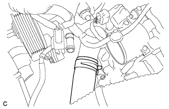
| 8. INSTALL OIL COOLER ASSEMBLY |
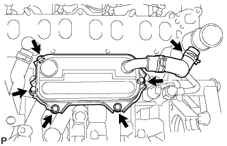
Install 3 new O-rings and oil cooler assembly with the 5 bolts.
- Torque:
- 11 N*m{ 112 kgf*cm, 8 ft.*lbf}
Connect the oil cooler hose.
| 9. INSTALL INTAKE MANIFOLD |
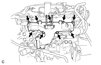
Install a new gasket and intake manifold with the 7 bolts and 2 nuts.
- Torque:
- 23 N*m{ 235 kgf*cm, 17 ft.*lbf}
| 10. INSTALL INTAKE MANIFOLD STAY |
Install the 2 bolts and intake manifold stay.
- Torque:
- 21 N*m{ 214 kgf*cm, 16 ft.*lbf}
| 11. INSTALL DIESEL THROTTLE BODY ASSEMBLY |
Install a new gasket and the diesel throttle body with the 2 nuts and 2 bolts.
- Torque:
- 21 N*m{ 214 kgf*cm, 16 ft.*lbf}
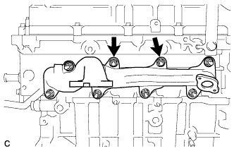
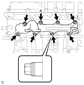
| 12. INSTALL OIL LEVEL GAUGE GUIDE |
Install a new O-ring to the oil level gauge.
Install the oil level gauge with the 3 bolts in the sequence shown in the illustration.
- Torque:
- Bolt 1:
- 11 N*m{ 112 kgf*cm, 8 ft.*lbf}
- Bolt 2:
- 20 N*m{ 204 kgf*cm, 15 ft.*lbf}
- Bolt 3:
- 40 N*m{ 408 kgf*cm, 30 ft.*lbf}
| 13. INSTALL GLOW PLUG ASSEMBLY |
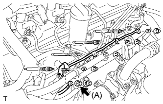
Install the 4 glow plugs.
- Torque:
- 12 N*m{ 125 kgf*cm, 9 ft.*lbf}
Install the glow plug connector with the 4 nuts.
- Torque:
- 2.2 N*m{ 22 kgf*cm, 19 in.*lbf}
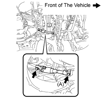
Install the wire harness with the nut (A).
- Torque:
- 4.0 N*m{ 41 kgf*cm, 35 in.*lbf}
Install the 5 grommets.
| 14. INSTALL INJECTOR ASSEMBLY |
- HINT:
- .
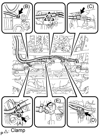
| 15. INSTALL COMMON RAIL ASSEMBLY |
- NOTICE:
- In cases where the common rail is replaced, the fuel inlet pipe and injection pipe must also be replaced.
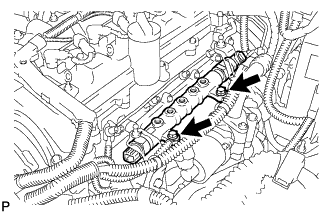
Temporarily install the common rail assembly with the 2 bolts.
Temporarily install the 2 fuel inlet pipes.
Temporarily install the No. 1, No. 2, No. 3 and No. 4 injection pipes.
Tighten the common rail assembly with the 2 bolts.
- Torque:
- 21 N*m{ 210 kgf*cm, 15 ft.*lbf}
Remove the No. 1, No. 2, No. 3 and No. 4 injection pipes.
Remove the 2 fuel inlet pipes.
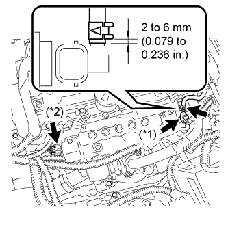
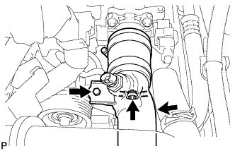
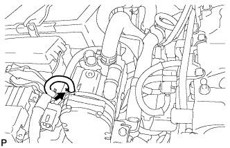
Connect the pressure discharge valve connector (*1).
Connect the fuel pressure sensor connector (*2).
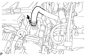
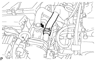
Using pliers, slide the clip to connect the fuel hose as shown in the illustration.
| 16. INSTALL VACUUM PUMP ASSEMBLY |
- HINT:
- .
| 17. INSTALL EGR VALVE ASSEMBLY |
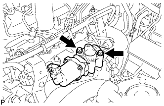
Install a new gasket and EGR valve assembly with the 2 bolts.
- Torque:
- 24 N*m{ 245 kgf*cm, 18 ft.*lbf}
| 18. TEMPORARILY TIGHTEN EXHAUST MANIFOLD |
Install a new gasket.
Temporarily tighten the 2 nuts and 2 collars for the exhaust manifold so that the seating surface of exhaust manifold is in touch with the cylinder head.
| 19. INSTALL TURBOCHARGER SUB-ASSEMBLY |
- HINT:
- .
| 20. INSTALL EXHAUST MANIFOLD |
Install the exhaust manifold and the 8 collars with 8 new nuts.
- Torque:
- 47 N*m{ 479 kgf*cm, 35 ft.*lbf}
- HINT:
Install the 2 bolts and exhaust manifold heat insulator.
- Torque:
- 25 N*m{ 255 kgf*cm, 18 ft.*lbf}
| 21. INSTALL EGR COOLER ASSEMBLY |
- HINT:
- .
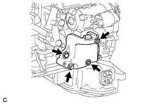
| 22. INSTALL NO. 1 COMPRESSOR MOUNTING BRACKET |
Install the No. 1 compressor mounting bracket to the engine block.
- Torque:
- 25 N*m{ 255 kgf*cm, 18 ft.*lbf}
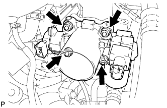
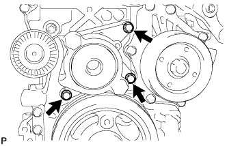
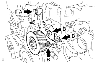
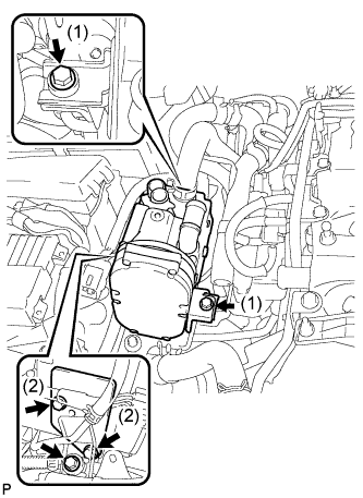
| 23. INSTALL COMPRESSOR ASSEMBLY WITH PULLEY |
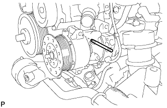
Temporarily install the compressor assembly with pulley onto the stud bolt.
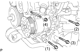
Install the compressor assembly with pulley with the 3 bolts and nut.
- Torque:
- 25 N*m{ 255 kgf*cm, 18 ft.*lbf}
- NOTICE:
- Tighten the bolts in the order shown in the illustration to install the compressor assembly with pulley.
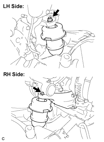
| 24. INSTALL ENGINE MOUNTING BRACKET LH |
Install the engine mounting bracket LH with the 4 bolts.
- Torque:
- 59 N*m{ 602 kgf*cm, 44 ft.*lbf}
| 25. INSTALL ENGINE MOUNTING BRACKET RH |
Install the engine mounting bracket RH with the 4 bolts.
- Torque:
- 59 N*m{ 602 kgf*cm, 44 ft.*lbf}
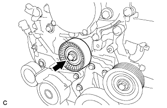
| 26. INSTALL V-RIBBED BELT TENSIONER ASSEMBLY |
Install the tensioner assembly with the 3 bolts.
- Torque:
- 20 N*m{ 204 kgf*cm, 15 ft.*lbf}
| 27. INSTALL NO. 1 IDLER PULLEY SUB-ASSEMBLY |
Install the idler pulley sub-assembly with the bolt.
- Torque:
- 40 N*m{ 408 kgf*cm, 30 ft.*lbf}
Install the idler pulley cover plate.
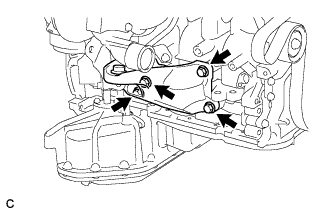
| 28. INSTALL IDLER PULLEY BRACKET |
Set the idler pulley bracket.
Install 4 bolts.
- Torque:
- Bolt A:
- 28 N*m{ 286 kgf*cm, 21 ft.*lbf}
- Bolt B:
- 80 N*m{ 816 kgf*cm, 59 ft.*lbf}
| 29. INSTALL GENERATOR ASSEMBLY |
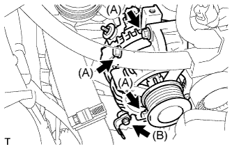
Install the clamp bracket to the generator assembly with the bolt (B).
- Torque:
- 10 N*m{ 102 kgf*cm, 7 ft.*lbf}
Install the generator assembly with the 3 bolts (A).
- Torque:
- 25 N*m{ 255 kgf*cm, 18 ft.*lbf}
- NOTICE:
- Make sure that the wire harness of the crankshaft position sensor does not get caught between the cylinder block and the generator assembly when installing the generator assembly.
Connect the clamp to the clamp bracket.
Install the wire harness to terminal B with the nut.
- Torque:
- 9.8 N*m{ 100 kgf*cm, 87 in.*lbf}
Install the wire harness clamp bracket with the bolt.
- Torque:
- 10 N*m{ 102 kgf*cm, 7 ft.*lbf}
Connect the generator connector.
| 30. INSTALL VACUUM SWITCHING VALVE BRACKET |
Install the 4 bolts and vacuum switching valve bracket.
- Torque:
- 9.0 N*m{ 92 kgf*cm, 80 in.*lbf}
| 31. INSTALL VACUUM REGULATING VALVE |
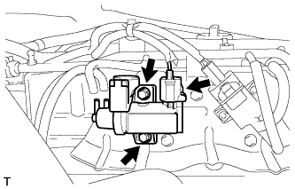
Install the vacuum regulating valve assembly with the 2 bolts.
- Torque:
- 9.0 N*m{ 92 kgf*cm, 80 in.*lbf}
Connect the vacuum regulating valve assembly connector.
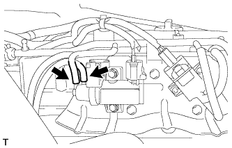
Connect the 2 vacuum hoses.
| 32. INSTALL NO. 1 VACUUM SWITCHING VALVE ASSEMBLY |
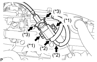
Using a hexagon socket wrench, install the No. 1 vacuum switching valve and 2 bolts (*1).
- Torque:
- 5.0 N*m{ 51 kgf*cm, 44 in.*lbf}
Connect the 2 vacuum hoses (*2).
Connect the vacuum switching valve connector (*3).
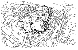
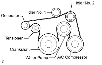
| 33. INSTALL V-RIBBED BELT |
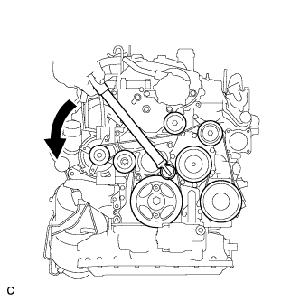
Install the V-ribbed belt.
While turning the belt tensioner counterclockwise, remove the bar.
- NOTICE:
After installing the V-ribbed belt, check that it fits properly in the ribbed grooves. Check to confirm that the belt has not slipped out of the grooves on the bottom of the crank pulley by hand.
After installing a new belt, run the engine for approximately 5 minutes and then recheck the tension.
If it is difficult to install the V-ribbed belt, perform the following procedure.
Put the V-ribbed belt on every part except the tensioner pulley as shown in the illustration.
While releasing the belt tension by turning the belt tensioner counterclockwise, put the V-ribbed belt on the tensioner pulley.
- NOTICE:
| 34. INSTALL ENGINE WIRE |
Install the engine wire to the engine assembly.
| 35. REMOVE ENGINE STAND |
| 36. INSTALL FRONT SUSPENSION CROSSMEMBER SUB-ASSEMBLY |
Install the front suspension crossmember sub-assembly to the engine with the 2 nuts.
- Torque:
- 35 N*m{ 357 kgf*cm, 26 ft.*lbf}
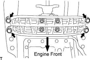
| 37. INSTALL FLYWHEEL SUB-ASSEMBLY |
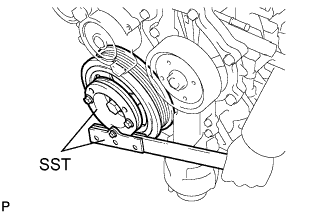
Hold the crankshaft with SST.
- SST
- 09213-58013
09330-00021
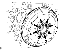
Install and tighten 8 new bolts a little at a time uniformly in the sequence shown in the illustration.
- Torque:
- 73 N*m{ 741 kgf*cm, 54 ft.*lbf}
- HINT:
Be sure to check the tightening torque within 5 minutes after tightening.
| 38. INSTALL CLUTCH DISC ASSEMBLY |
- HINT:
- .
| 39. INSTALL MANUAL TRANSAXLE ASSEMBLY |
- HINT:
- .
| 40. INSTALL CLUTCH RELEASE CYLINDER ASSEMBLY |
| 41. INSTALL CLUTCH ACCUMULATOR ASSEMBLY |
| 42. INSTALL STARTER ASSEMBLY |
Install the starter assembly with the bolt and nut.
- Torque:
- 64 N*m{ 650 kgf*cm, 47 ft.*lbf}
Connect the wire harness to terminal 30 and install the nut, and then attach the terminal cap.
- Torque:
- 9.8 N*m{ 100 kgf*cm, 87 in.*lbf}
Connect the terminal 50 connector to the starter assembly.
Install the wire harness clamp bracket with the bolt.
- Torque:
- 10 N*m{ 102 kgf*cm, 7 ft.*lbf}
Connect the 2 wire harness clamps.
| 43. INSTALL EXHAUST MANIFOLD CONVERTER SUB-ASSEMBLY |
.
| 44. INSTALL ENGINE ASSEMBLY WITH TRANSMISSION |
Set the engine lifter.
Operate the engine lifter, then install the engine to the vehicle.
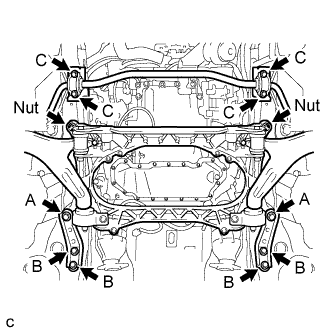
Install the engine and transmission assembly with crossmember with the 12 bolts.
- Torque:
- Nut:
- 167 N*m{ 1,700 kgf*cm, 123 ft.*lbf}
- Torque:
- Bolt A:
- 204 N*m{ 2,080 kgf*cm, 150 ft.*lbf}
- Bolt B:
- 50 N*m{ 510 kgf*cm, 37 ft.*lbf}
- Bolt C:
- 49 N*m{ 500 kgf*cm, 36 ft.*lbf}
Install the engine rear mounting member with the 4 bolts.
- Torque:
- 26 N*m{ 265 kgf*cm, 19 ft.*lbf}
| 45. INSTALL FLOOR SHIFT LEVER ASSEMBLY |
.
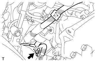
| 46. CONNECT POWER STEERING LINK WIRE HARNESS |
Install the power steering ground wire to the power steering link assembly with bolt (B).
- Torque:
- 13 N*m{ 130 kgf*cm, 10 ft.*lbf}
Connect the wire harness connector (E) to the power steering link assembly and securely lock the connector.
Connect the 2 wire harness connectors (C) and (D) to the power steering link assembly.
Install the 2 wire harness clamps to the power steering link assembly.
Connect the earth wire to the bracket with bolt (A).
- Torque:
- 5.0 N*m{ 51 kgf*cm, 44 in.*lbf}
| 47. INSTALL FRONT LOWER BALL JOINT ASSEMBLY LH |
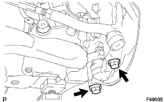
Install the front lower ball joint with the 2 bolts.
- Torque:
- 120 N*m{ 1,224 kgf*cm, 89 ft.*lbf}
| 48. INSTALL FRONT LOWER BALL JOINT ASSEMBLY RH |
- HINT:
- Install the RH side following the same procedure as for the LH side.
| 49. INSTALL FRONT SHOCK ABSORBER ASSEMBLY LH |
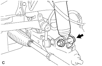
Install the bolt on the lower side of the front shock absorber while holding the nut.
- Torque:
- 157 N*m{ 1,600 kgf*cm, 116 ft.*lbf}
| 50. INSTALL FRONT SHOCK ABSORBER ASSEMBLY RH |
- HINT:
- Install the RH side following the same procedure as for the LH side.
| 51. INSTALL HEIGHT CONTROL SENSOR LINK |
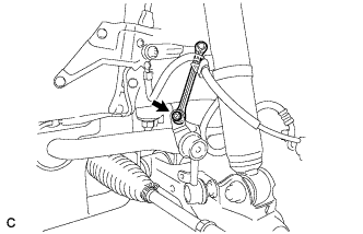
Connect the height control sensor link and install it with the nut.
- Torque:
- 5.4 N*m{ 55 kgf*cm, 48 in.*lbf}
| 52. CONNECT STEERING SLIDING WITH SHAFT YOKE SUB-ASSEMBLY |
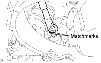
Align the matchmarks on the steering sliding yoke sub-assembly and the power steering gear assembly.
Install bolt (A) and tighten the 2 bolts.
- Torque:
- 35 N*m{ 360 kgf*cm, 26 ft.*lbf}
| 53. CONNECT NO. 3 FUEL HOSE |

Install the clamp and connect the No. 3 fuel hose.
| 54. CONNECT FUEL HOSE |
Install the clamp and connect the fuel hose.
| 55. CONNECT ENGINE WIRE |
Connect the 2 wire harness clamps and 3 injector connectors.
Install the bolt, clamp and engine wire No. 3.
- Torque:
- 8.5 N*m{ 87 kgf*cm, 75 in.*lbf}
Connect the connector and install the 3 clamps to the body.
Connect the wire to the engine room No. 1 junction block. Then, install it with the nut.
- Torque:
- 12 N*m{ 124 kgf*cm, 9 ft.*lbf}
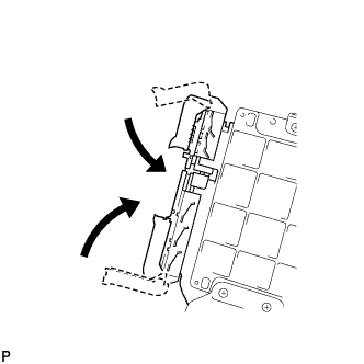
Install the engine room No. 1 relay block cover.
Connect the battery positive (+) terminal and install it with the nut.
- Torque:
- 13 N*m{ 133 kgf*cm, 10 ft.*lbf}
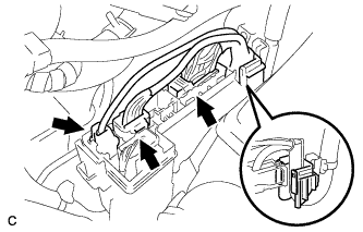
Connect the 2 ECM connectors and lower the 2 levers.
- NOTICE:
Connect the engine wire to the engine room junction block.
Install the relay block cover.
| 56. INSTALL DIFFERENTIAL PRESSURE SENSOR ASSEMBLY |
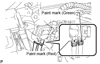
Connect the No. 1 vacuum transmitting hose and No. 2 vacuum transmitting hose.
- HINT:
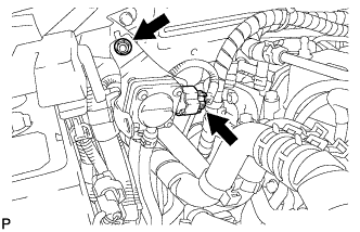
Install the differential pressure sensor with the nut.
- Torque:
- 8.0 N*m{ 82 kgf*cm, 71 in.*lbf}
Connect the differential pressure sensor connector.
| 57. CONNECT DISCHARGE HOSE SUB-ASSEMBLY |
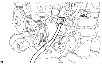
Remove the attached vinyl tape from the hose.
Apply sufficient compressor oil to a new O-ring and the fitting surface of the compressor assembly with pulley.
- Compressor oil:
- ND-OIL 8 or equivalent
Install the O-ring onto the discharge hose sub-assembly.
Install the discharge hose sub-assembly onto the compressor assembly with pulley with the bolt.
- Torque:
- 9.8 N*m{ 100 kgf*cm, 87 in.*lbf}
| 58. CONNECT NO. 1 COOLER REFRIGERANT SUCTION HOSE |
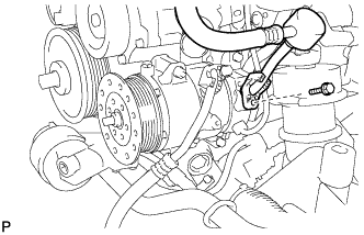
Remove the attached vinyl tape from the hose.
Apply sufficient compressor oil to a new O-ring and the fitting surface of the compressor and magnetic clutch.
- Compressor oil:
- ND-OIL 8 or equivalent
Install the O-ring onto the No. 1 cooler refrigerant suction hose.
Install the No. 1 cooler refrigerant suction hose onto the compressor and magnetic clutch with the bolt.
- Torque:
- 9.8 N*m{ 100 kgf*cm, 87 in.*lbf}
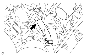
| 59. INSTALL NO. 1 AIR HOSE |
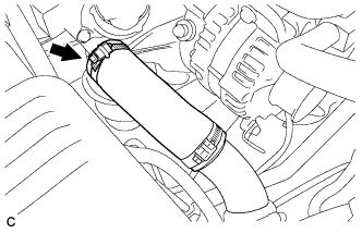
Install the clamp and connect the No. 1 air hose.
| 60. CONNECT HEATER WATER INLET HOSE |
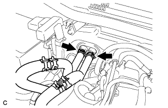
Connect the heater water inlet hose.
| 61. CONNECT HEATER WATER OUTLET HOSE |
Connect the heater water outlet hose.
| 62. CONNECT RADIATOR OUTLET HOSE |
Connect the radiator outlet hose.
| 63. CONNECT RESERVE TANK OUTLET HOSE |
Connect the radiator reserve tank hose.
| 64. CONNECT VACUUM TRANSMITTING HOSE |
Connect the vacuum transmitting hose.
| 65. INSTALL AIR PIPE SUB-ASSEMBLY |
Connect the wire harness clamp.
Install the air pipe sub-assembly with the bolt.
- Torque:
- 5.0 N*m{ 51 kgf*cm, 44 in.*lbf}
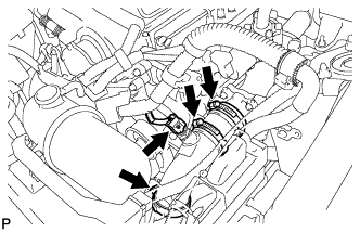
Connect the intake air temperature sensor connector.
Tighten the 3 hose bands.
- Torque:
- 4.0 N*m{ 41 kgf*cm, 35 in.*lbf}
Connect the 2 diesel throttle body connectors.
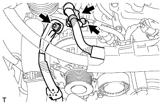
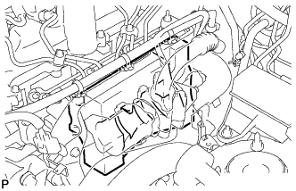
| 66. INSTALL NO. 1 WATER OUTLET PIPE |
Install the No. 1 water outlet pipe with the 3 bolts.
- Torque:
- 21 N*m{ 214 kgf*cm, 16 ft.*lbf}
Connect the 2 water hoses with the 2 bands.
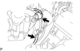
Connect the manifold absolute pressure sensor connector and vacuum hose.
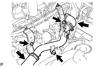
| 67. INSTALL NO. 2 EGR PIPE |
Install the intake manifold insulator.
- HINT:
- Insert the intake manifold insulator between the EGR valve and common rail to make contact with the intake manifold.
Install 2 new gaskets.
Temporarily install No. 2 EGR pipe with the bolt and nut.
Temporarily install the bolt and tighten the 2 bolts.
- Torque:
- 24 N*m{ 245 kgf*cm, 18 ft.*lbf}
Temporarily install the nut and tighten the 2 nuts.
- Torque:
- 24 N*m{ 245 kgf*cm, 18 ft.*lbf}
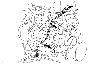
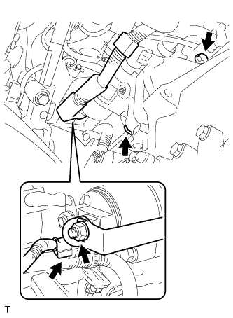
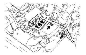
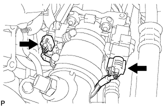
| 68. INSTALL WIRING HARNESS CLAMP BRACKET |
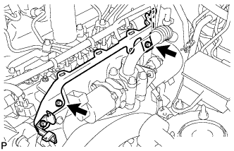
Install the wiring harness clamp bracket with the 2 bolts.
- Torque:
- 10 N*m{ 102 kgf*cm, 7 ft.*lbf}
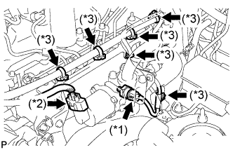
Connect the oil pressure switch assembly connector (*1).
Connect the EGR valve connector (*2).
Connect the 6 wire harness clamps (*3).
Connect the wire harness clamp.
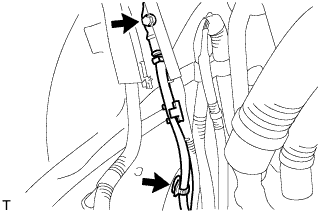
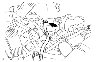
| 69. CONNECT UNION TO CHECK VALVE HOSE |
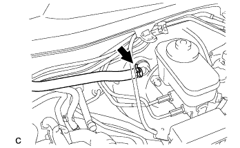
Install the clamp and connect the union to the check valve hose.
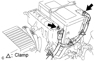
| 70. INSTALL HEATER ASSEMBLY (with Combustion Type Power Heater) |
Install the heater assembly with the 4 bolts.
- Torque:
- Bolt 1:
- 9.8 N*m{ 100 kgf*cm, 7 ft.*lbf}
- Bolt 2:
- 5.4 N*m{ 55 kgf*cm, 48 in.*lbf}
Install the fuel hose and attach the clip.
Install the heater water outlet hose and attach the clip.
Install the heater water inlet hose and attach the clip.
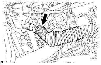
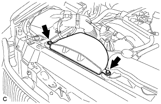
| 71. INSTALL AIR DUCT (with Combustion Type Power Heater) |
Install the air duct with the clip and clamp.
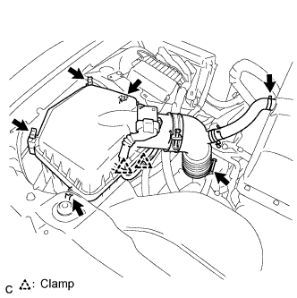
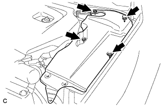
| 72. INSTALL AIR CLEANER CASE SUB-ASSEMBLY |
Install the air cleaner case, clamp and 2 bolts.
- Torque:
- 5.0 N*m{ 51 kgf*cm, 44 in.*lbf}
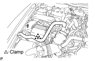
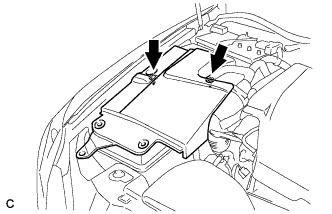
| 73. INSTALL AIR CLEANER CAP WITH AIR CLEANER HOSE |
Install the air cleaner cap with air cleaner hose assembly with the 4 clamps and hose clamp.
- HINT:
- Be sure to install the air cleaner assembly so that the screw part of the hose clamp is as shown in the illustration.
Connect the ventilation hose to the cylinder head cover with the clamp.
Connect the MAF meter connector and 2 clamps to the air cleaner.
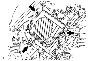
| 74. INSTALL NO. 1 INLET AIR CLEANER |
Install the inlet air cleaner with the bolt and clip.
- Torque:
- 5.0 N*m{ 51 kgf*cm, 44 in.*lbf}
| 75. INSTALL PROPELLER SHAFT ASSEMBLY WITH CENTER BEARING |
.
| 76. INSTALL FRONT EXHAUST PIPE ASSEMBLY |
- HINT:
- .
| 77. ADD ENGINE OIL |
Install the oil pan drain plug with a new gasket.
- Torque:
- 38 N*m{ 388 kgf*cm, 28 ft.*lbf}
Add engine oil according to the table below.
- Standard capacity:
Item Capacity Drain and refill with oil filter change 6.0 liters (6.3 US qts, 5.3 lmp. qts) Drain and refill without oil filter change 5.2 liters (5.5 US qts, 4.6 lmp. qts) Dry fill 6.7 liters (7.1 US qts, 5.9 lmp. qts)
| 78. CONNECT NEGATIVE BATTERY TERMINAL |
- Torque:
- 5.4 N*m{ 55 kgf*cm, 48 in.*lbf}
| 79. ADD ENGINE COOLANT |
Tighten all the plugs.
- Torque:
- for cylinder block drain cock plug:
- 20 N*m{ 204 kgf*cm, 15 ft.*lbf}
Add engine coolant.
- Specified capacity:
- 8.9 liters (9.4 US qts, 7.8 lmp. qts)
- HINT:
Slowly pour coolant into the radiator reservoir until it reaches the FULL line.
Squeeze the inlet and outlet radiator hoses several times by hand, and then check the level of the coolant.
If the coolant level is low, add coolant.
Install the radiator cap.
Bleed air from the cooling system.
- NOTICE:
- Before starting the engine, turn the A/C switch off.
Warm up the engine until the thermostat opens. While the thermostat is open, allow the coolant to circulate for several minutes.
- HINT:
- The thermostat open timing can be confirmed by squeezing the inlet radiator hose by hand, and sensing vibrations when the engine coolant starts to flow inside the hose.
- NOTICE:
- When squeezing the radiator hose:
Maintain the engine speed at 2,000 to 2,500 rpm.
Squeeze the inlet and outlet radiator hoses several times by hand to bleed air from the system.
- NOTICE:
- When squeezing the radiator hoses:
Stop the engine and wait until the engine coolant cools down to ambient temperature.
- CAUTION:
- Do not remove the radiator cap while the engine and radiator are still hot. Pressurized, hot engine coolant and steam may be released and cause serious burns.
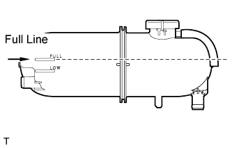
Check the coolant level in the reserve tank.
If the coolant level is low, add coolant to the reserve tank FULL line.
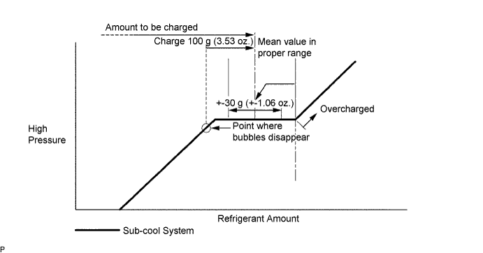
| 80. CHARGE REFRIGERANT |
Perform vacuum purging using a vacuum pump.
Charge refrigerant HFC-134a (R134a).
- Standard:
- 430 +- 30 g (15.17 +- 1.06 oz.)
- SST
- 07110-58060(07117-58060,07117-58070,07117-58080,07117-58090,07117-78050,07117-88060,07117-88070,07117-88080)
- NOTICE:
| 81. CHECK FOR CLUTCH FLUID LEAKS |
| 82. CHECK FOR ENGINE OIL LEAKS |
| 83. CHECK FOR ENGINE COOLANT LEAKS |
- CAUTION:
- Do not remove the radiator cap while the engine and radiator are still hot. Pressurized, hot engine coolant and steam may be released and cause serious burns.
- NOTICE:
- Before performing each inspection, turn the A/C switch off.
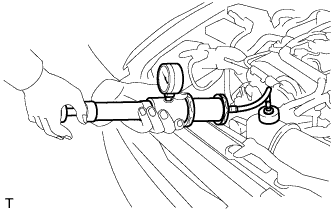
Fill the radiator with coolant and attach a radiator cap tester.
Warm up the engine.
Using a radiator cap tester, increase the pressure inside the radiator to 177 kPa (1.8 kgf/cm, 26 psi), and check that the pressure does not drop.
If the pressure drops, check the hoses, radiator and water pump for leaks. If no external leaks are found, check the heater core, cylinder block and cylinder head.
| 84. CHECK FOR FUEL LEAKS |
PERFORM ACTIVE TEST
Connect the intelligent tester to the DLC3.
Turn the engine switch ON (IG).
Turn the intelligent tester ON.
Enter the following menus: Powertrain / ENGINE / Active Test.
Perform the Active Test.
| Intelligent Tester Display | Test Details | Control Range | Diagnostic Notes |
| Test the Fuel Leak | Pressurize common rail internal fuel pressure, and check for fuel leaks | Stop/Start | Fuel pressure inside common rail pressurized to specified value and engine speed increased to 2,000 rpm when "Start" is selected Above conditions to be maintained while "Start" is selected |
| 85. CHECK FOR EXHAUST GAS LEAKS |
| 86. CHECK FOR REFRIGERANT LEAKS |
After recharging the refrigerant gas, check for refrigerant gas leakage using a halogen leak detector.
Perform the operation under the following conditions:
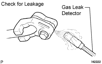
Using a gas leak detector, check the refrigerant line for leakage.
If a gas leak is not detected on the drain hose, remove the blower motor control (blower resistor) from the cooling unit. Insert the gas leak detector sensor into the unit and perform the test.
Disconnect the connector and leave the pressure switch on for approximately 20 minutes. Bring the gas leak detector close to the pressure switch and perform the test.
| 87. INSTALL FRONT WHEELS |
- Torque:
- 103 N*m{ 1,050 kgf*cm, 76 ft.*lbf}
| 88. PLACE FRONT WHEELS FACING STRAIGHT AHEAD |
| 89. CHECK AND ADJUST FRONT WHEEL ALIGNMENT |
.
| 90. CHECK ENGINE IDLE SPEED |
- NOTICE:
Warm up and stop the engine.
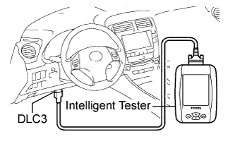
Connect the intelligent tester to the DLC3.
Turn the engine switch on (IG).
Select the items:
Powertrain / Engine / Data List / Engine SPD.
- HINT:
- Refer to the intelligent tester operation manual if you need help to select Data List.
Inspect the engine idle speed.
- Idle speed:
- 750 to 850 rpm
Turn the engine switch off.
Disconnect the intelligent tester from the DLC3.
| 91. CHECK ENGINE OIL LEVEL |
Warm up the engine, stop the engine and wait for 5 minutes. The oil level should be between the low and full level marks of the dipstick.
If the level is below the low level mark, check for leakage and add oil until it reaches the full level mark.
- NOTICE:
- Do not fill the engine oil above the full level mark.
| 92. INSTALL ENGINE UNDER COVER REAR LH |
Install the engine under cover rear LH with the bolt.
| 93. INSTALL ENGINE UNDER COVER REAR RH |
- HINT:
- Install the RH side following the same procedure as for the LH side.
| 94. INSTALL ENGINE UNDER COVER AIR GUIDE BRACKET |
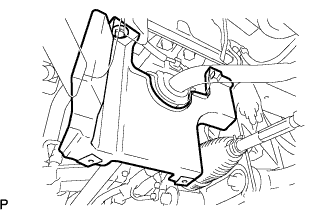
| 95. INSTALL FRONT LOWER SUSPENSION MEMBER PROTECTOR |
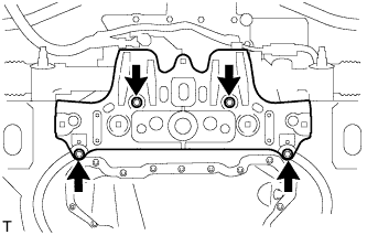
Install the protector with the 4 bolts.
- Torque:
- 8.0 N*m{ 82 kgf*cm, 71 in.*lbf}
| 96. INSTALL NO. 2 ENGINE UNDER COVER |
| 97. INSTALL ENGINE UNDER COVER |
| 98. INSTALL NO. 1 ENGINE COVER |
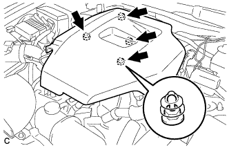
Install the No. 1 engine cover.
| 99. INSTALL ENGINE ROOM SIDE COVER LH |
Install the side cover with the 4 clips.
| 100. INSTALL ENGINE ROOM SIDE COVER RH |
Install the side cover with the 2 clips.
| 101. INSTALL COOL AIR INTAKE DUCT SEAL |

Install the intake duct seal with the 11 clips.
| 102. PERFORM INITIALIZATION |
Perform initialization procedure .
- HINT:
- Some vehicle systems require initialization after reconnecting the negative battery terminal.