Lexus IS250 IS220d GSE20 ALE20 2AD-FHV ENGINE CONTROL SYSTEM
CHECK CONNECTION BETWEEN INTELLIGENT TESTER AND ECM
CHECK THROTTLE BODY ASSEMBLY (CHECK MIL ILLUMINATED)
CHECK ACCELERATOR PEDAL ASSEMBLY (CHECK MIL ILLUMINATED)
CHECK FUEL PRESSURE SENSOR (CHECK MIL ILLUMINATED)
CHECK EGR VALVE POSITION SENSOR (CHECK MIL ILLUMINATED)
CHECK MANIFOLD ABSOLUTE PRESSURE SENSOR (CHECK MIL ILLUMINATED)
CHECK DIFFERENTIAL PRESSURE SENSOR (CHECK MIL ILLUMINATED)
CHECK BATTERY CURRENT SENSOR ASSEMBLY (CHECK MIL ILLUMINATED)
ECD SYSTEM - VC Output Circuit
DESCRIPTION
The ECM constantly generates 5 V power from the battery voltages supplied to the +B (BATT) terminal to operate the microprocessor. The ECM also provides this power to the sensors through the VC output circuit.
When the VC circuit is short-circuited, the microprocessor in the ECM and sensors that are supplied power through the VC circuit are inactivated because the power is not supplied from the VC circuit. Under this condition, the system does not start up and the MIL does not illuminate even if the system malfunctions.
- HINT:
- Under normal conditions, the MIL is illuminated for several seconds when the engine switch is first turned on (IG). The MIL goes off when the engine is started.
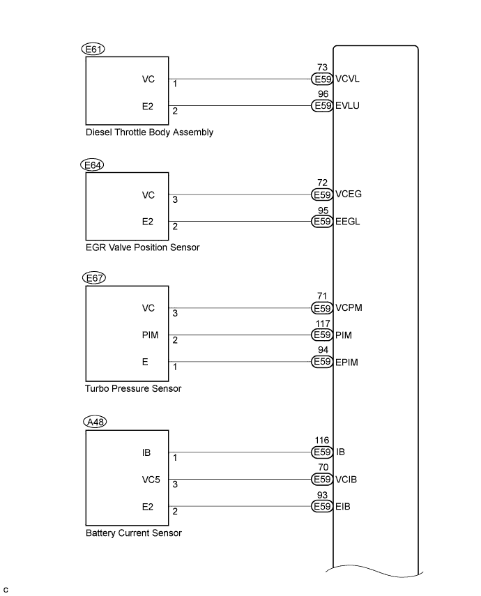
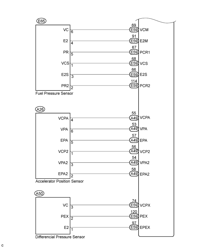
WIRING DIAGRAM
INSPECTION PROCEDURE
| 1.CHECK MIL |
Check that Malfunction Indicator Lamp (MIL) lights up when turning the engine switch on (IG).
- OK:
- MIL lights up.
|
| ||||
| NG | |
| 2.CHECK CONNECTION BETWEEN INTELLIGENT TESTER AND ECM |
Connect the intelligent tester to the DLC3.
Turn the engine switch on (IG) and tester ON.
Check the communication between the tester and ECM.
- Result:
Result Proceed to Communication is possible A Communication is not possible B
|
| ||||
| B | |
| 3.CHECK THROTTLE BODY ASSEMBLY (CHECK MIL ILLUMINATED) |
Disconnect the throttle body connector.
Turn the engine switch on (IG).
Check the MIL.
- Result:
Result Proceed to MIL illuminates A MIL does not illuminate B
Reconnect the throttle body connector.
|
| ||||
| B | |
| 4.CHECK ACCELERATOR PEDAL ASSEMBLY (CHECK MIL ILLUMINATED) |
Disconnect the accelerator pedal position sensor connector.
Turn the engine switch on (IG).
Check the MIL.
- Result:
Result Proceed to MIL illuminates A MIL does not illuminate B
Reconnect the accelerator pedal position sensor connector.
|
| ||||
| B | |
| 5.CHECK FUEL PRESSURE SENSOR (CHECK MIL ILLUMINATED) |
Disconnect the fuel pressure sensor connector.
Turn the engine switch on (IG).
Check the MIL.
- Result:
Result Proceed to MIL illuminates A MIL does not illuminate B
Reconnect the fuel pressure sensor connector.
|
| ||||
| B | |
| 6.CHECK EGR VALVE POSITION SENSOR (CHECK MIL ILLUMINATED) |
Disconnect the EGR valve position sensor connector.
Turn the engine switch on (IG).
Check the MIL.
- Result:
Result Proceed to MIL illuminates A MIL does not illuminate B
Reconnect the EGR valve position sensor connector.
|
| ||||
| B | |
| 7.CHECK MANIFOLD ABSOLUTE PRESSURE SENSOR (CHECK MIL ILLUMINATED) |
Disconnect the manifold absolute pressure sensor connector.
Turn the engine switch on (IG).
Check the MIL.
- Result:
Result Proceed to MIL illuminates A MIL does not illuminate B
Reconnect the manifold absolute pressure sensor connector.
|
| ||||
| B | |
| 8.CHECK DIFFERENTIAL PRESSURE SENSOR (CHECK MIL ILLUMINATED) |
Disconnect the differential pressure sensor connector.
Turn the engine switch on (IG).
Check the MIL.
- Result:
Result Proceed to MIL illuminates A MIL does not illuminate B
Reconnect the differential pressure sensor connector.
|
| ||||
| B | |
| 9.CHECK BATTERY CURRENT SENSOR ASSEMBLY (CHECK MIL ILLUMINATED) |
Disconnect the battery current sensor connector.
Turn the engine switch on (IG).
Check the MIL.
- Result:
Result Proceed to MIL illuminates A MIL does not illuminate B
Reconnect the battery current sensor connector.
|
| ||||
| B | |
| 10.CHECK HARNESS AND CONNECTOR |
Disconnect the throttle body connector.
Disconnect the accelerator pedal position sensor connector.
Disconnect the EGR valve position sensor connector.
Disconnect the manifold absolute pressure sensor connector.
Disconnect the differential pressure sensor connector.
Disconnect the fuel pressure sensor connector.
Disconnect the battery current sensor connector.
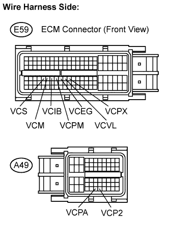
Disconnect the E59 and A49 ECM connectors.
Check the resistance.
- Standard resistance (Check for short):
Tester Connections Specified Conditions VCS (E59-68) - Body ground 10 kΩ or higher VCM (E59-69) - Body ground VCIB (E59-70) - Body ground VCPM (E59-71) - Body ground VCEG (E59-72) - Body ground VCPA (A49-55) - Body ground VCP2 (A49-56) - Body ground VCVL (E59-73) - Body ground VCPX (E59-74) - Body ground
Reconnect the ECM connectors.
Reconnect the fuel pressure sensor connector.
Reconnect the battery current sensor connector.
Reconnect the differential pressure sensor connector.
Reconnect the manifold absolute pressure sensor connector.
Reconnect the EGR position sensor connector.
Reconnect the accelerator pedal position sensor connector.
Reconnect the throttle body connector.
|
| ||||
| OK | ||
| ||