Lexus IS250 IS220d GSE20 ALE20 2AD-FHV ENGINE CONTROL SYSTEM
ECD SYSTEM - TERMINALS OF ECM
- HINT:
- Each ECM terminal's standard voltage is shown in the table below.
- In the table, first follow the information in "Condition". Look "Symbols (Terminal No.)" for the terminals to be inspected. The standard voltage between the terminals is shown in "Specified Condition".
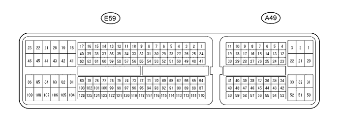
- Use the illustration above as a reference for the ECM terminals.
| Symbols (Terminal No.) | Wiring Color | Terminal Description | Condition | Specified Condition |
| BATT (A49-2) - E1 (E59-109) | L - BR | Battery (for measuring the battery voltage and for the ECM memory) | Always | 9 to 14 V |
| IGSW (A49-25) - E1 (E59-109) | B-W - BR | Engine switch | Engine switch ON (IG) | 9 to 14 V |
| STSW (A49-9) - E1 (E59-109) | Y-B - BR | Engine switch | Engine switch ON (START) | 9 to 14 V |
| +B (A49-1) - E1 (E59-109) | B-R - BR | Power source of ECM | Engine switch ON (IG) | 9 to 14 V |
| MREL (A49-45) - E1 (E59-109) | Y - BR | MAIN relay | Engine switch ON (IG) | 9 to 14 V |
| MREL (A49-45) - E1 (E59-109) | Y - BR | MAIN relay | 2 seconds elapsed after engine switch OFF | 0 to 1.5 V |
| VCVL (E59-73) - EVLU (E59-96) | V-W - BR-W | Power source of throttle position sensor | Engine switch ON (IG) | 4.5 to 5.5 V |
| VCEG (E59-72) - EEGL (E59-95) | V-Y - GR-L | Power source of EGR position sensor | Engine switch ON (IG) | 4.5 to 5.5 V |
| VCM (E59-69) - E2M (E59-91) | V - G-B | Power source of fuel pressure sensor | Engine switch ON (IG) | 4.5 to 5.5 V |
| VCIB (E59-70) - EIB (E59-93) | LG - BR | Power source of battery current sensor | Engine switch ON (IG) | 4.5 to 5.5 V |
| VCPX (E59-74) - EPEX (E59-97) | R-W - BR | Power source of differential pressure sensor | Engine switch ON (IG) | 4.5 to 5.5 V |
| VCPM (E59-71) - EPIM (E59-94) | V - Y-G | Power source of manifold absolute pressure sensor | Engine switch ON (IG) | 4.5 to 5.5 V |
| ACCR (A49-24) - E1 (E59-109) | W-L - BR | ACC cut signal | Engine switch ON (ACC or IG) | 9 to 14 V |
| ACCR (A49-24) - E1 (E59-109) | W-L - BR | ACC cut signal | Cranking | 0 to 1.5 V |
| VPA (A49-53) - EPA (A49-57) | G-W - L-Y | Accelerator pedal position sensor (for engine control) | Engine switch ON (IG), accelerator pedal fully released | 0.5 to 1.1 V |
| VPA (A49-53) - EPA (A49-57) | G-W - L-Y | Accelerator pedal position sensor (for engine control) | Engine switch ON (IG), accelerator pedal fully depressed | 3.0 to 4.6 V |
| VPA2 (A49-54) - EPA2 (A49-58) | P-L - G-B | Accelerator pedal position sensor (for sensor malfunction detection) | Engine switch ON (IG), accelerator pedal fully depressed | 0.9 to 2.3 V |
| VPA2 (A49-54) - EPA2 (A49-58) | P-L - G-B | Accelerator pedal position sensor (for sensor malfunction detection) | Engine switch ON (IG), accelerator pedal fully released | 3.4 to 5.0 V |
| VCPA (A49-55) - EPA (A49-57) | P - L-Y | Power source of accelerator pedal position sensor (for VPA1) | Engine switch ON (IG) | 4.5 to 5.5 V |
| VCP2 (A49-56) - EPA2 (A49-58) | G-R - G-B | Power source of accelerator pedal position sensor (for VPA2) | Engine switch ON (IG) | 4.5 to 5.5 V |
| VG (E59-65) - EVG (E59-64) | G - L-Y | Mass air flow meter | Idling, A/C switch off | 0.5 to 3.4 V |
| THA (E59-110) - ETHA (E59-87) | G-R - O | IAT sensor | Idling, intake air temperature at 0 to 80°C (32 to 176°F) | 0.5 to 3.4 V |
| THW (E59-111) - ETHW (E59-88) | G-R - O | ECT sensor | Idling, engine coolant temperature at 60 to 120°C (140 to 248°F) | 0.2 to 1.0 V |
| IB (E59-116) - E1B (E59-93) | W-L - BR | Battery current sensor | Engine switch ON (IG) | 0.5 to 4.5 V |
| THB (E59-115) - ETHB (E59-92) | LG-B - BR | Battery thermometer sensor | Engine switch ON (IG) | 0.5 to 4.5 V |
| STA (E59-43) - E1 (E59-109) | R-B - BR | Starter signal | Cranking | 6.0 V or more |
| STAR (E59-53) - E1 (E59-109) | L - BR | Starter drive request signal | Cranking | 9 to 14 V |
| #1 (E59-50) - E1 (E59-109) #2 (E59-49) - E1 (E59-109) #3 (E59-48) - E1 (E59-109) #4 (E59-47) - E1 (E59-109) | G-W - BR R-Y - BR LG-B - BR Y-B - BR | Injector | Idling | Pulse generation (see waveform 2) |
| G+ (E59-80) - G- (E59-79) | G - L | Camshaft position sensor | Idling | Pulse generation (see waveform 4) |
| NE+ (E59-78) - NE- (E59-77) | G - R | Crankshaft position sensor | Idling | Pulse generation (see waveform 4) |
| STP (A49-35) - E1 (E59-109) | R-B - BR | Normally open switch | Engine switch ON (IG), brake pedal depressed | 7.5 to 14 V |
| STP (A49-35) - E1 (E59-109) | R-B - BR | Normally open switch | Engine switch ON (IG), brake pedal released | 0 to 1.5 V |
| ST1- (A49-34) - E1 (E59-109) | G-W - BR | Normally closed switch | Engine switch ON (IG), brake pedal depressed | 0 to 1.5 V |
| ST1- (A49-34) - E1 (E59-109) | G-W - BR | Normally closed switch | Engine switch ON (IG), brake pedal released | 7.5 to 14 V |
| TC (A49-26) - E1 (E59-109) | V - BR | Terminal TC of DLC3 | Engine switch ON (IG) | 9 to 14 V |
| W (A49-12) - E1 (E59-109) | R-L - BR | MIL | MIL illuminated | 0 to 3 V |
| W (A49-12) - E1 (E59-109) | R-L - BR | MIL | MIL not illuminated | 9 to 14 V |
| SPD (A49-14) - E1 (E59-109) | Y-G - BR | Speed signal from combination meter | Engine switch ON (IG), drive wheels are rotating slowly | Pulse generation (see waveform 7) |
| PIM (E59-117) - EPIM (E59-94) | W-R - Y-G | Manifold absolute pressure sensor | Apply negative pressure of 40 kPa (300 mmHg, 11.8 in.Hg) | 0.3 to 0.9 V |
| PIM (E59-117) - EPIM (E59-94) | W-R - Y-G | Manifold absolute pressure sensor | Same as atmospheric pressure | 0.8 to 1.4 V |
| PIM (E59-117) - EPIM (E59-94) | W-R - Y-G | Manifold absolute pressure sensor | Apply positive pressure of 69 kPa (518 mmHg, 20.3 in.Hg) | 1.6 to 2.2 V |
| IREL (A49-44) - E1 (E59-109) | W - BR | EDU relay | Engine switch OFF | 9 to 14 V |
| IREL (A49-44) - E1 (E59-109) | W - BR | EDU relay | Idling | 0 to 1.5 V |
| TACH (A49-13) - E1 (E59-109) | R-W - BR | Engine speed | Idling | Pulse generation (see waveform 8) |
| VCS (E59-68) - E2S (E59-66) | GR - L-B | Common rail pressure sensor | Engine switch ON (IG) | 4.5 to 5.5 V |
| PCR1 (E59-67) - E2M (E59-91) | P - G-B | Common rail pressure sensor (main) | Idling | 1.8 to 2.1 V |
| PCR2 (E59-114) - E2S (E59-66) | P-L - G-B | Common rail pressure sensor (sub) | Idling | 1.2 to 1.5 V |
| GREL (E59-56) - E1 (E59-109) | G - BR | Glow plug relay | Cranking | 9 to 14 V |
| GREL (E59-56) - E1 (E59-109) | G - BR | Glow plug relay | Idling (Engine start after 10 minutes or more) | 0 to 1.5 V |
| THF (E59-112) - ETHF (E59-89) | L-R - G-R | Fuel temperature sensor | Engine switch ON (IG) | 0.5 to 3.4 V |
| ALT (E59-54) - E1 (E59-109) | P - BR | Generator duty ratio | Idling | Pulse generation (see waveform 9) |
| PCV+ (E59-42) - PCV- (E59-41) | LG-B - LG | Suction control valve | Idling | Pulse generation (see waveform 1) |
| PRD (E59-52) - E1 (E59-109) | R-L - BR | Pressure relief valve drive signal | Engine switch OFF | 4 to 6.5 V |
| INJF (E59-51) - E1 (E59-109) | R-B - BR | EDU | Idling | Pulse generation (see waveform 3) |
| VN (E59-84) - E1 (E59-109) | Y - BR | VRV (for VN turbocharger) | Engine switch ON (IG) | Pulse generation (see waveform 5) |
| VLU (E59-119) - EVLU (E59-96) | L-W - BR-W | Throttle position sensor | Engine switch ON (IG), throttle valve fully opened | 2.8 to 3.8 V |
| LUSL (E59-86) - E1 (E59-109) | G-R - BR | Throttle valve duty signal | Engine warmed up, engine racing | Pulse generation (see waveform 6) |
| EGLS (E59-118) - EEGL (E59-95) | R-G - GR-L | EGR valve position sensor | Engine switch ON (IG) | 0.6 to 1.4 V |
| FIV (E59-105) - E1 (E59-109) | L-R - BR | Exhaust fuel addition injector | Engine warmed up, idling, every 1 to 2 minutes | Pulse generation |
| THCO (E59-121) - ETCO (E59-98) | B-Y - B-R | Exhaust gas temperature sensor | Engine warmed up, Idling | 4.6 to 4.9 V |
| THCI (E59-122) - ETCI (E59-99) | B - B-W | |||
| PEX (E59-120) - EPEX (E59-97) | W - BR | Differential pressure sensor | Engine switch ON (IG) | 0.4 to 4.8 V |
| AF2+ (E59-103) - E1 (E59-109) | R - BR | A/F sensor | Engine switch ON (IG) | 2.0 to 2.5 V |
| AF2- (E59-126) - E1 (E59-109) | W - BR | A/F sensor | Engine switch ON (IG) | 2.0 to 2.5 V |
| EGRS (E59-85) - E1 (E59-109) | G-B - BR | EGR | Engine warmed up, idling | Pulse generation (see waveform 10) |
| HAF2 (E59-104) - E05 (E59-46) | L-B - W-B | A/F sensor heater | Engine switch ON (IG) | 9 to 14 V |
| VG (E59-65) - EVG (E59-64) | G - L-Y | MAF meter power source | Engine idling | 0.5 to 3.4 V |
| FANH (E59-21) - E1 (E59-109) | GR - BR | Radiator fan relay | Radiator fan stopped | 9 to 14 V |
| FANH (E59-21) - E1 (E59-109) | GR - BR | Radiator fan relay | Operate radiator fan | 0 to 1.5 V |
| FANL (A49-22) - E1 (E59-109) | W - BR | Radiator fan relay | Radiator fan stopped | 9 to 14 V |
| FANL (A49-22) - E1 (E59-109) | W - BR | Radiator fan relay | Operate radiator fan | 0 to 1.5 V |
| THIA (E59-113) - ETHI (E59-90) | GR - BR-Y | Intake air temperature sensor (Intake manifold) | Idling, intake air temperature at 0 to 80°C (32 to 176°F) | 0.5 to 3.4 V |
| IDLO (E59-62) - E1 (E59-109) | W-G - BR | Idling signal | Engine idling | 3.4 V or more |
| IDLO (E59-62) - E1 (E59-109) | W-G - BR | Idling signal | Engine speed higher than idling | 0.05 V or less |
| FC (E59-83) - E1 (E59-109) | R-W - BR | Fuel pump control | Operate fuel pump | 0 to 1.5V |
| FC (E59-83) - E1 (E59-109) | R-W - BR | Fuel pump control | Fuel pump stopped | 9 to 14 V |
| MPPM (A49-18) - E1 (E59-109) | L-R - BR | Fuel route switching valve monitor | Fuel route switching valve ON | 9 to 14 V |
| MPPM (A49-18) - E1 (E59-109) | L-R - BR | Fuel route switching valve monitor | Fuel route switching valve OFF | 0 to 1.5 V |
| PPRM (E59-107) - E1 (E59-109) | L-W - BR | Fuel route switching valve control | Fuel route switching valve ON | 0 to 1.5 V |
| PPRM (E59-107) - E1 (E59-109) | L-W - BR | Fuel route switching valve control | Fuel route switching valve OFF | 9 to 14 V |
| CANH (A49-38) - E1 (E59-109) | B - BR | CAN communication line | Engine switch ON (IG) | Pulse generation (see waveform 11) |
| CANL (A49-46) - E1 (E59-109) | W - BR | CAN communication line | Engine switch ON (IG) | Pulse generation (see waveform 12) |
| Waveform 1 |
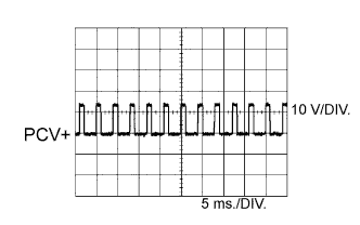
Suction control valve signal
| Symbols (Terminal No.) | PCV+ (E59-42) - PCV- (E59-41) |
| Tool Setting | 10 V/DIV., 5 ms./DIV. |
| Condition | Idling or cranking with warm engine |
- HINT:
- The waveform varies depending on the suction control valve operation.
| Waveform 2 |
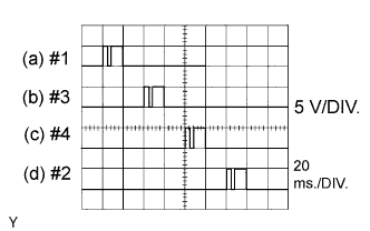
Injector No. 1 injection signal
Injector No. 2 injection signal
Injector No. 3 injection signal
Injector No. 4 injection signal
| Symbols (Terminal No.) | (a) #1 (E59-50) - E1 (E59-109) (b) #3 (E59-48) - E1 (E59-109) (c) #4 (E59-47) - E1 (E59-109) (d) #2 (E59-49) - E1 (E59-109) |
| Tool Setting | 5 V/DIV., 20 ms./DIV. |
| Condition | Idling with warm engine |
- HINT:
- The waveform varies depending on the injector injection.
| Waveform 3 |
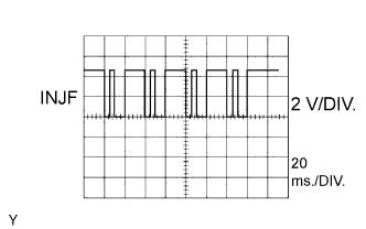
Injector injection confirmation signal
| Symbols (Terminal No.) | INJF (E59-51) - E1 (E59-109) |
| Tool Setting | 2 V/DIV., 20 ms./DIV. |
| Condition | Idling with warm engine |
- HINT:
- The waveform varies depending on the injector injection.
| Waveform 4 |
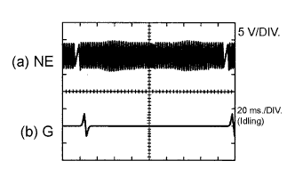
Crankshaft position sensor signal
Camshaft position sensor signal
| Symbol (Terminal No.) | (a) NE+ (E59-78) - NE- (E59-77) (b) G+ (E59-80) - G- (E59-79) |
| Tool Setting | 5 V/DIV., 20 ms./DIV. |
| Condition | Idling with warm engine |
- HINT:
- The waveform varies depending on the engine revolution.
| Waveform 5 |
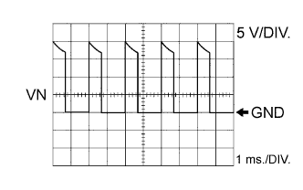
E-VRV for turbocharger control signal
| Symbols (Terminal No.) | VN (E59-84) - E1 (E59-109) |
| Tool Setting | 5 V/DIV., 1 ms./DIV. |
| Condition | Idling with warm engine |
- HINT:
- The waveform changes depending on the electric vacuum regulating valve for turbocharger operation.
| Waveform 6 |
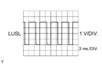
Diesel throttle signal
| Symbols (Terminal No.) | LUSL (E59-86) - E1 (E59-109) |
| Tool Setting | 1 V/DIV., 2 ms./DIV. |
| Condition | Warm engine with engine racing |
- HINT:
- The waveform varies depending on the throttle valve operation.
| Waveform 7 |
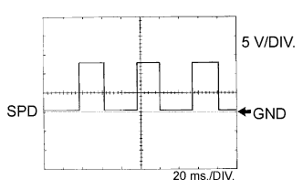
Vehicle speed signal
| Symbols (Terminal No.) | SPD (A49-14) - E1 (E59-109) |
| Tool Setting | 5 V/DIV., 20 ms./DIV. |
| Condition | Driving the vehicle |
- HINT:
- The wavelength becomes shorter as the vehicle speed increases.
| Waveform 8 |
Engine speed signal
| Symbols (Terminal No). | TACH (A49-13) - E1 (E59-109) |
| Tool Setting | 5 V/DIV., 20 ms./DIV. |
| Condition | Idling with warm engine |
- HINT:
- The wavelength becomes shorter as the engine speed increases.
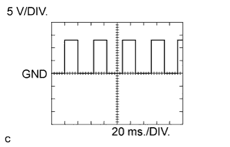
| Waveform 9 |

Generator signal
| Symbols (Terminal No). | ALT (E59-54) - E1 (E59-109) |
| Tool Setting | 5 V/DIV., 5 ms./DIV. |
| Condition | Idling |
| Waveform 10 |
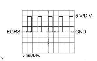
EGR position sensor signal
| Symbols (Terminal No). | EGRS (E59-85) - E1 (E59-109) |
| Tool Setting | 5 V/DIV., 5 ms./DIV. |
| Condition | Idling |
| Waveform 11 |
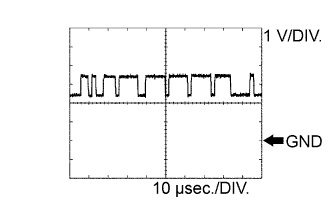
CAN communication signal
| Symbols (Terminal No). | CANH (A49-38) - E1 (E59-109) |
| Tool Setting | 1 V/DIV., 10 μsec./DIV. |
| Condition | Engine not running and engine switch on (IG) |
- HINT:
- The waveform varies depending on the CAN communication signal.
| Waveform 12 |
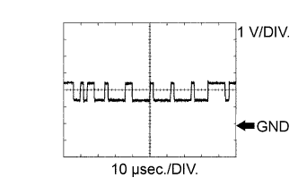
CAN communication signal
| Symbols (Terminal No). | CANL (A49-46) - E1 (E59-109) |
| Tool Setting | 1 V/DIV., 10 μsec./DIV. |
| Condition | Engine not running and engine switch on (IG) |
- HINT:
- The waveform varies depending on the CAN communication signal.