Lexus IS250 IS220d GSE20 ALE20 2AD-FHV ENGINE CONTROL SYSTEM
CHECK FUEL GAUGE OPERATION (FUEL PUMP OPERATION)
PERFORM ACTIVE TEST BY INTELLIGENT TESTER (OPERATE F/PMP RELAY)
PERFORM ACTIVE TEST BY INTELLIGENT TESTER (OPERATE F/PMP RELAY)
CHECK HARNESS AND CONNECTOR (F/PMP RELAY - FUEL PUMP RESISTER)
CHECK HARNESS AND CONNECTOR (FUEL PUMP - F/PMP RELAY)
ECD SYSTEM - Fuel Pump Control Circuit
DESCRIPTION
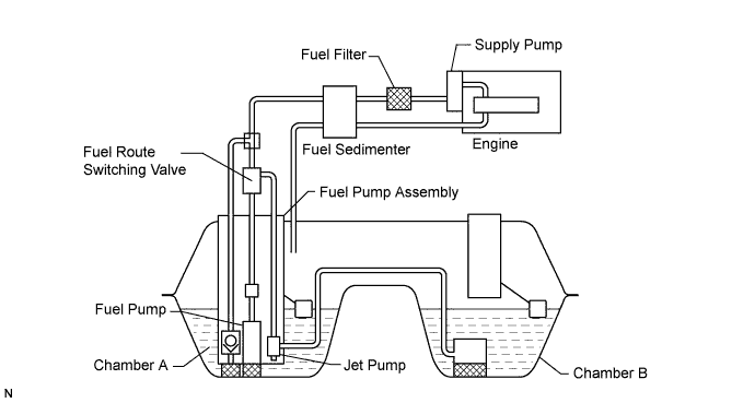
A fuel pump is located in the fuel tank and controlled by the ECM. The fuel pump operates only when fuel transfer operation and priming operation are performed.
Fuel transfer operation:
When the fuel level in fuel tank chamber A decreases, the ECM activates the fuel pump to transfer the fuel from chamber B to chamber A to keep the fuel level in chamber A above the specified level.
Priming operation:
The ECM turns on the three-way valve, changing the route of the fuel. Then the fuel pump is operated by the ECM in order to send the fuel from the fuel pump to the fuel supply pump in order to bleed air from the supply pump and fuel inlet pipe.
WIRING DIAGRAM

INSPECTION PROCEDURE
| 1.CHECK FUEL GAUGE OPERATION (FUEL PUMP OPERATION) |
Connect the intelligent tester to the DLC3.
Turn the engine switch ON (IG) and turn the tester ON.
Enter the following menus: Body / Combination Meter / Data List / Fuel Input and Sub Fuel Gauge.
Read the value.
- NG:
- Fuel Input:
- 158 or more
- Sub Fuel Gauge:
- 123 or less
|
| ||||
| NG | |
| 4.INSPECT F/PMP RELAY |
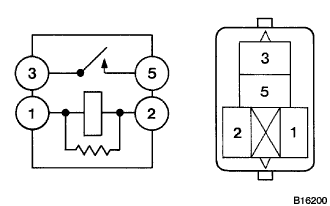
Remove the F/PMP relay from the engine room J/B and R/B No. 2.
Measure the resistance of the F/PMP relay.
- Standard resistance:
Tester Connection Specified Condition 3 - 5 10 kΩ or higher 3 - 5 Below 1 Ω
(when battery voltage applied to terminals 1 and 2)
|
| ||||
| OK | |
| 5.CHECK HARNESS AND CONNECTOR (F/PMP RELAY - FUEL PUMP RESISTER) |
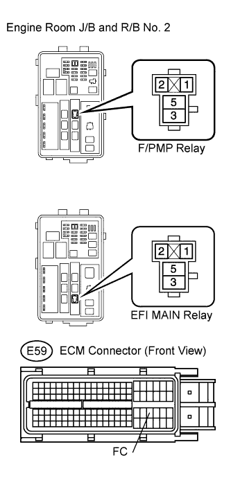
Remove the F/PMP relay and EFI MAIN relay from the engine room J/B and R/B No. 2.
Disconnect the E59 ECM connector.
Measure the resistance of the wire harness side connectors.
- Standard resistance (Check for open):
Tester Connection Specified Condition F/PMP relay (1) - EFI MAIN relay (3) Below 1 Ω F/PMP relay (2) - FC (E59-83) Below 1 Ω
- Standard resistance (Check for short):
Tester Connection Specified Condition Fuel pump relay (1) - Body ground 10 kΩ or higher Fuel pump relay (2) - Body ground 10 kΩ or higher
Reinstall the F/PMP relay and EFI MAIN relay.
Reconnect the ECM connector.
|
| ||||
| NG | ||
| ||
| 6.INSPECT FUEL PUMP |
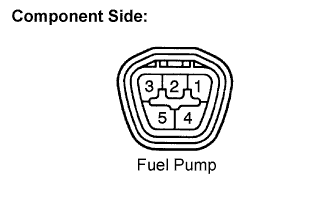
Inspect fuel pump resistance.
Measure the resistance between terminals 4 and 5.
- Standard resistance:
- 0.2 to 3.0 Ω at 20°C (68°F)
Inspect fuel pump operation.
Apply battery voltage to both the terminals. Check that the pump operates.
- NOTICE:
|
| ||||
| OK | |
| 7.CHECK TERMINAL VOLTAGE |
Connect the intelligent tester to the DLC3.
Turn the engine switch ON (IG) and turn the tester ON.
Enter the following menus: Powertrain / Engine / Active Test / Activate the Intank Fuel Pump Relay.
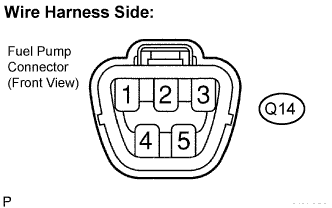
Measure the voltage of the fuel pump connector.
- Standard voltage:
Tester Connection Condition Specified Condition Q14-4 - Q14-5 Relay ON 9 to 14 V
|
| ||||
| NG | |
| 8.CHECK HARNESS AND CONNECTOR (FUEL PUMP - F/PMP RELAY) |
Check the harness and the connectors between the fuel pump and the F/PMP relay.
Disconnect the fuel pump connector.
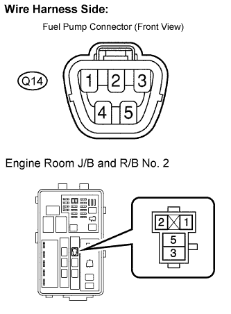
Remove the F/PMP relay from the engine room J/B and R/B No. 2.
Measure the resistance of the wire harness side connectors.
- Standard resistance (Check for open):
Tester Connection Specified Condition Fuel pump (Q14-4) - F/PMP relay (3) Below 1 Ω
- Standard resistance (Check for short):
Tester Connection Specified Condition Fuel pump (Q14-4) or F/PMP (3) - Body ground 10 kΩ or higher
Check the harness and the connectors between the fuel pump and the body ground.
Disconnect the fuel pump connector.
Measure the resistance of the wire harness side connector and the body ground.
- Standard resistance (Check for open):
Tester Connection Specified Condition Fuel pump (Q45-5) - Body ground 10 kΩ or higher
|
| ||||
| OK | ||
| ||