Lexus IS250 IS220d GSE20 ALE20 2AD-FHV ENGINE CONTROL SYSTEM
CHECK HARNESS AND CONNECTOR (ENGINE WIRE HARNESS)
PERFORM CONFIRMATION DRIVING PATTERN
READ DTC OUTPUT (RELATING TO ENGINE)
PERFORM ACTIVE TEST BY INTELLIGENT TESTER (TEST THE FUEL LEAK)
READ VALUE OF INTELLIGENT TESTER (MAP, MAF AND FUEL PRESSURE)
READ VALUE OF INTELLIGENT TESTER (INJECTION FEED BACK VAL AND INJECTION VOLUME)
CHECK INJECTOR COMPENSATION CODE
INSPECT DIESEL THROTTLE BODY ASSEMBLY
PERFORM ACTIVE TEST BY INTELLIGENT TESTER (FUEL CUT FOR IDENTIFYING MALFUNCTION)
CHECK CYLINDER COMPRESSION PRESSURE
CHECK INJECTOR (MALFUNCTIONING CYLINDER'S INJECTOR FOR DEPOSITS)
READ VALUE OF INTELLIGENT TESTER (INJECTION FEEDBACK VAL AND INJECTION VOLUME)
CHECK INJECTOR ASSEMBLY (IDENTIFY MALFUNCTIONING CYLINDER INJECTOR)
PERFORM ACTIVE TEST BY INTELLIGENT TESTER (FUEL CUT FOR IDENTIFYING MALFUNCTIONING CYLINDER)
CHECK INJECTORS FOR DEPOSITS (EXCEPT FUEL ADDITION INJECTOR)
READ VALUE OF INTELLIGENT TESTER (INJECTION FEEDBACK VAL AND INJECTION VOLUME)
CONFIRM WHETHER MALFUNCTION HAS BEEN SUCCESSFULLY REPAIRED
INSPECT COMMON RAIL ASSEMBLY (FUEL PRESSURE SENSOR)
ECD SYSTEM - Engine Knocking or Rattling
DESCRIPTION
| Malfunction Condition | Main Trouble Areas | Related Trouble Areas |
Knocking and abnormal sound due to extremely rich combustion Abnormal sound due to friction between parts | Injector malfunctions Injector sliding malfunction Injector stuck closed Injector stuck open Deposits in injector Injector circuit malfunction Abnormal common rail pressure Supply pump Fuel pulsation sound Air in fuel Friction between parts Compression pressure | Injector compensation codes Fuel leakage Intake air system leakage Intake air system blockage EGR system Throttle valve system Fuel pressure sensor Manifold absolute pressure sensor Atmosphere air pressure sensor (built into ECM) Vehicle modifications Low quality fuel Lack of fuel ECM |
- HINT:
INSPECTION PROCEDURE
- NOTICE:
- HINT:
| 1.CHECK ENGINE SOUND |
Find source of the abnormal sound using a mechanic's stethoscope.
- Result:
Result Proceed to Sound from supply pump A Sound from parts other than supply pump B
|
| ||||
|
| ||||
| A | |
| 7.READ VALUE OF INTELLIGENT TESTER (INJECTION FEED BACK VAL AND INJECTION VOLUME) |
Select the following menu items in order and read the values.
- Standard:
Item Engine Speed* Standard Range Description Injection Feedback Val #1 Idling -3.0 to 3.0 mm3 Value of injector fuel injection volume compensates for differences in combustion condition of cylinders Positive values indicate control which corrects combustion degradationNegative values indicate control which corrects excessive combustion pressureIf problems exist, Injection Feedback Val may deviate from -3.0 and 3.0 mm rangeInjection Feedback Val #2 Idling -3.0 to 3.0 mm3 Injection Feedback Val #3 Idling -3.0 to 3.0 mm3 Injection Feedback Val #4 Idling -3.0 to 3.0 mm3 Injection Volume Idling 3.9 to 7.0 mm3 Fuel injection volume value controlled by ECU Controls NE signal, fuel temperature, engine coolant temperature, intake air temperature, boost pressure, atmospheric pressure, and EGR volume.If problems exist, Injection Volume may be outside standard range
- Result:
Result Proceed to Standard range A Injection Feedback Val #1 to #4 and/or Injection Volume outside standard range B
- HINT:
- *: The A/C switch and all accessory switches should be OFF, and the engine should be fully warmed up.
|
| ||||
| A | |
| 8.CHECK INJECTOR COMPENSATION CODE |
- HINT:
- If the injector compensation code is not correctly registered, it may cause malfunctions .
- OK:
- Compensation code of the installed injector is the same as the code registered in the ECM.
|
| ||||
| A | |
| 14.PERFORM ACTIVE TEST BY INTELLIGENT TESTER (FUEL CUT FOR IDENTIFYING MALFUNCTION) |
Connect the intelligent tester to the DLC3.
Start the engine and turn the intelligent tester ON.
Enter the following menus: Powertrain / Engine / Active Test / Control the Cylinder #1, #2, #3, and #4 Fuel Cut.
Check the four cylinders in sequence to identify any faulty cylinders by performing the power balance inspection.
- HINT:
| NEXT | |
| 15.CHECK CYLINDER COMPRESSION PRESSURE |
Check the cylinder compression pressure .
- Standard:
- 2,700 kPa (27.5 kgf/cm2, 392 psi)
- Minimum pressure:
- 2,200 kPa (22.4 kgf/cm2, 319 psi)
- Difference between each cylinder:
- 500 kPa (5.1 kgf/cm2, 73 psi)
|
| ||||
|
| ||||
| A | |
| 20.PERFORM ACTIVE TEST BY INTELLIGENT TESTER (FUEL CUT FOR IDENTIFYING MALFUNCTIONING CYLINDER) |
Connect the intelligent tester to the DLC3.
Start the engine and turn the intelligent tester ON.
Enter the following menus: Powertrain / Engine / Active Test / Control the Cylinder #1, #2, #3, and #4 Fuel Cut.
Check the four cylinders in sequence to identify any faulty cylinders by performing the power balance inspection.
- HINT:
| NEXT | ||
| ||
| 21.CHECK INJECTORS FOR DEPOSITS (EXCEPT FUEL ADDITION INJECTOR) |
- HINT:
- If an injector is contaminated with deposits, the fuel injection volume deviates from the standard range. This may cause malfunctions.
Check the injector for any deposits.
- Result:
Injector Condition Proceed to Deposits A No Deposits B
|
| ||||
| A | |
| 22.CLEAN INJECTOR |
Wipe away deposits from the tips of the injectors.
- HINT:
| NEXT | |
| 23.READ VALUE OF INTELLIGENT TESTER (INJECTION FEEDBACK VAL AND INJECTION VOLUME) |
Reinstall the injector to the cylinder head.
Connect the intelligent tester to the DLC3.
Turn the engine switch ON (IG) and turn the intelligent tester ON.
Start the engine and warm it up.
Enter the following menus: Powertrain / Engine / Data List.
Select the following menu items in order and read the values displayed on the intelligent tester respectively.
- Standard:
Item Engine Speed* Reference Value Injection Feedback Val #1 to #4 Idling -3.0 to 3.0 mm3 Injection Volume Idling 3.9 to 7.0 mm3
*: The A/C switch and all accessory switches should be OFF, and the engine should be fully warmed up.
- HINT:
- When the values are outside the standard range, deposits inside the injector may be causing the problem.
- OK:
- Values are within the standard range.
|
| ||||
| OK | ||
| ||
| 24.BLEED AIR FROM FUEL SYSTEM |
To bleed air from the priming pump, pump the priming pump until it becomes hard and cannot be pumped any more.
| NEXT | |
| 25.CONFIRM WHETHER MALFUNCTION HAS BEEN SUCCESSFULLY REPAIRED |
Check whether the knocking has been successfully repaired by performing a driving test.
- OK:
- Malfunction has been repaired successfully.
| NEXT | ||
| ||
| 26.INSPECT COMMON RAIL ASSEMBLY (FUEL PRESSURE SENSOR) |
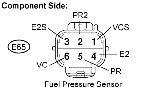
Disconnect the E65 fuel sensor connector.
Measure the resistance between each terminal of the fuel pressure sensor connector.
- Standard resistance:
Tester Connection Specified Condition PR (E65-5) - E2 (E65-4) 16.4 kΩ or less PR2 (E65-2) - E2S (E65-3) 16.4 kΩ or less PR (E65-5) - VC (E65-6) 3 kΩ or less PR2 (E65-2) - VCS (E65-1) 3 kΩ or less
Reconnect the fuel pressure sensor connector.
|
| ||||
| OK | |
| 27.INSPECT SUPPLY PUMP ASSEMBLY |
Measure the resistance of the suction control valve terminals.
- Standard resistance:
Condition Specified Condition 20°C (68°F) 1.9 to 2.3 Ω
|
| ||||
| OK | ||
| ||