Lexus IS250 IS220d GSE20 ALE20 2AD-FHV ENGINE CONTROL SYSTEM
CHECK OTHER DTC OUTPUT (IN ADDITION TO DTC P2237)
INSPECT AIR FUEL RATIO SENSOR (HEATER RESISTANCE)
CHECK HARNESS AND CONNECTOR (A/F SENSOR - ECM)
DTC P2237 Oxygen (A/F) Sensor Pumping Current Circuit / Open (Bank 1 Sensor 1)
DTC P2238 Oxygen (A/F) Sensor Pumping Current Circuit Low (Bank 1 Sensor 1)
DTC P2239 Oxygen (A/F) Sensor Pumping Current Circuit High (Bank 1 Sensor 1)
DTC P2252 Oxygen (A/F) Sensor Reference Ground Circuit Low (Bank 1 Sensor 1)
DTC P2253 Oxygen (A/F) Sensor Reference Ground Circuit High (Bank 1 Sensor 1)
DESCRIPTION
- HINT:
- *: Diesel Clean Advanced Technology.
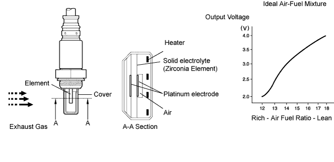
The A/F sensor has the characteristic of providing output voltage which is proportional to the existing air- fuel ratio. The A/F sensor output voltage (*1) is used to provide the ECM with feedback to control the air-fuel ratio.
The A/F sensor is located after the DPNR (*2) catalytic converter. This sensor has been developed based on structure and technology of a sensor that is being used for gasoline engines. The cover portion of the sensor has been changed for use in the diesel engine with TOYOTA D-CAT in order to eliminate the influence of the sensor temperature and particulate matter (PM).
In order to reduce both PM and nitrogen oxides (NOx), the ECM adjusts the air-fuel ratio to slightly RICH (but it is LEAN compared with a stoichiometric air-fuel ratio) based on signals from the A/F sensor. When the ECM exercises DPNR catalyst regeneration by adding fuel using the exhaust fuel addition injector, the air-fuel ratio is also properly adjusted through the sensor.
*1: The voltage value changes inside the ECM only.
*2: Diesel Particulate-NOx Reduction system.
- HINT:
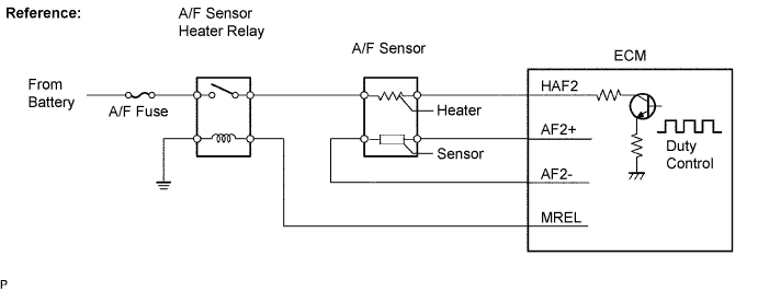
- The ECM provides a pulse width modulated control circuit to adjust current through the heater. The A/F sensor heater circuit uses a relay on the B+ side of the circuit.
| DTC No. | DTC Detection Condition | Trouble Area |
| P2237 | ECM internal error (5.0 seconds) (1 trip detection logic) |
ECM |
| P2238 P2252 |
A/F sensor circuit low (bank 1 sensor 1) AF+ is less than 1.0 V for 5.0 seconds or more (1 trip detection logic) |
Open or short in A/F sensor circuit A/F sensor A/F sensor heater A/F relay A/F sensor heater and relay circuit ECM |
| P2239 P2253 |
A/F sensor circuit high (bank 1 sensor 1) AF+ is more than 4.0 V for 5.0 seconds or more (1 trip detection logic) |
Open or short in A/F sensor circuit A/F sensor A/F sensor heater A/F relay A/F sensor heater and relay circuit ECM |
MONITOR DESCRIPTION
The A/F sensor varies its voltage output in proportion to the air-fuel ratio. If impedance (alternating current resistance) or voltage output of the sensor deviates greatly from the standard range, the ECM interprets this as an open or short in the A/F sensor circuit.
WIRING DIAGRAM

INSPECTION PROCEDURE
- NOTICE:
- After replacing the ECM, the new ECM needs registration and initialization .
| 1.CHECK OTHER DTC OUTPUT (IN ADDITION TO DTC P2237) |
Connect the intelligent tester to the DLC3.
Turn the engine switch ON (IG) and turn the intelligent tester ON.
Enter the following menus: "Powertrain / Engine / DTC".
Read DTCs.
- Result:
Display (DTC output) Proceed to P2237 and "P2238, P2239, P2252 and/or P2253" A P2237 B
|
| ||||
| A | |
| 2.INSPECT AIR FUEL RATIO SENSOR (HEATER RESISTANCE) |
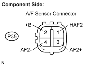
Disconnect the P35 A/F sensor connector.
Measure the resistance between the terminals of the A/F sensor.
- Standard resistance:
Tester Connection Condition Specified Condition +B (2) - HAF2 (1) 20°C (68°F) 1.8 to 3.4 Ω
Reconnect the A/F sensor connector.
|
| ||||
| OK | |
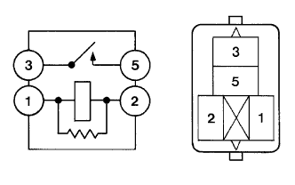
| 3.INSPECT A/F RELAY |
Remove the A/F relay.
Check for continuity in the A/F relay.
- Standard resistance:
Tester Connection Specified Condition 3 - 5 10 kΩ or higher Below 1 Ω
(Apply battery voltage to terminals 1 and 2)
Reinstall the A/F relay.
|
| ||||
| OK | |
| 4.CHECK HARNESS AND CONNECTOR (A/F SENSOR - ECM) |
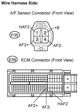
Disconnect the P35 A/F sensor connector.
Disconnect the E59 ECM connector.
Check the resistance between the wire harness side connectors.
- Standard resistance (Check for open):
Tester Connection Specified Condition AF2+ (P35-3) - AF2+ (E59-103) Below 1 Ω AF2- (P35-4) - AF2- (E59-126) Below 1 Ω HAF2 (P35-1) - HAF2 (E59-104) Below 1 Ω
- Standard resistance (Check for short):
Tester Connection Specified Condition AF2+ (P35-3) or AF2+ (E59-103) - Body ground 10 kΩ or higher AF2- (P35-4) or AF2- (E59-126) - Body ground 10 kΩ or higher HAF2 (P35-1) or HAF2 (E59-104) - Body ground 10 kΩ or higher
Reconnect the A/F sensor connector.
Reconnect the ECM connector.
|
| ||||
| OK | ||
| ||