Lexus IS250 IS220d GSE20 ALE20 2AD-FHV ENGINE CONTROL SYSTEM
READ VALUE OF INTELLIGENT TESTER (STARTER SIGNAL)
INSPECT CLUTCH START SWITCH ASSEMBLY
DTC P0617 Starter Relay Circuit High
DESCRIPTION
While the engine is being cranked, the positive battery voltage is applied to terminal STA of the ECM.
If the ECM detects the Starter Control (STA) signal while the vehicle is being driven, it determines that there is a malfunction in the STA circuit. The ECM then illuminates the MIL and sets the DTC.
This monitor runs when the vehicle is driven at 20 km/h (12.4 mph) for over 20 seconds.
| DTC No. | DTC Detection Condition | Trouble Area |
| P0617 | When conditions (a), (b) and (c) are met, positive (+B) battery voltage of 10.5 V or more is applied to ECM for 20 seconds (1 trip detection logic): (a) Vehicle speed more than 20 km/h (12.4 mph) (b) Engine speed more than 1,000 rpm (c) STA signal ON | Clutch start switch Cranking holding function circuit ECM |
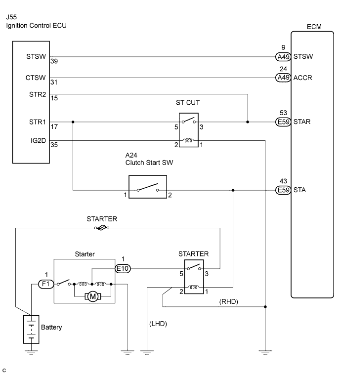
WIRING DIAGRAM
INSPECTION PROCEDURE
- HINT:
| 1.READ VALUE OF INTELLIGENT TESTER (STARTER SIGNAL) |
Connect the intelligent tester to the DLC3.
Turn the engine switch on (IG) and turn the tester ON.
Enter the following menus: Power train / Engine / Data List / Starter Signal.
Check the value displayed on the tester when the engine switch is turned on (IG) and when turned on (START).
- OK:
Engine Switch Condition ON START Starter Signal OFF ON
|
| ||||
| NG | |
| 2.INSPECT CLUTCH START SWITCH ASSEMBLY |
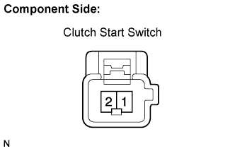
Remove the A24 clutch start switch.
Check the resistance between each pair of terminals.
- Standard resistance:
Switch Position Specified Condition Switch pin free 10 kΩ or higher Switch pin pushed in Below 1 Ω
Reinstall the clutch start switch.
|
| ||||
| OK | ||
| ||