Lexus IS250 IS220d GSE20 ALE20 2AD-FHV EMISSION CONTROL
EXHAUST MANIFOLD CONVERTER - INSTALLATION
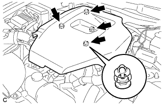
| 1. INSTALL NO. 1 MANIFOLD CONVERTER INSULATOR |
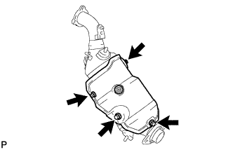
Install the No. 1 manifold converter insulator with the 3 bolts and nut.
- Torque:
- 25 N*m{ 255 kgf*cm, 18 ft.*lbf}
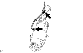
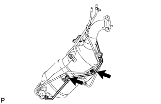
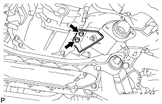
| 2. INSTALL NO. 2 VACUUM PIPE |
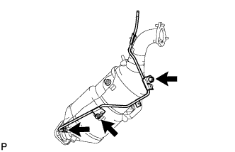
Temporarily install the No. 2 vacuum pipe with the bolt and nut.
Tighten the bolt and nut.
- Torque:
- 18 N*m{ 184 kgf*cm, 13 ft.*lbf}
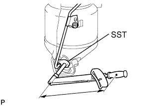
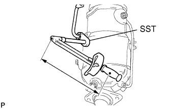
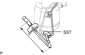
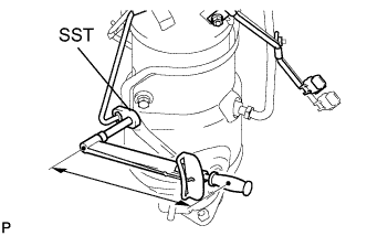
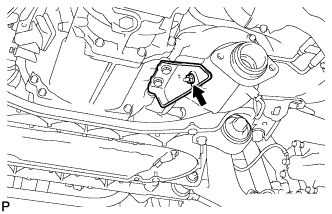
Using SST, tighten the nut of the No. 2 vacuum pipe.
- SST
- 09023-38401
- Torque:
- 30 N*m{ 306 kgf*cm, 22 ft.*lbf}
- HINT:
- Use a torque wrench with a fulcrum length of 30 cm (11.81 in.).
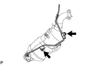
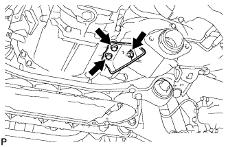
| 3. INSTALL NO. 1 VACUUM PIPE |
Temporarily install the No. 1 vacuum pipe with the nut.
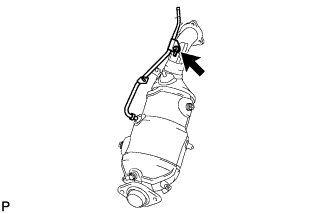
Tighten the nut.
- Torque:
- 18 N*m{ 184 kgf*cm, 13 ft.*lbf}
Using SST, tighten the nut of the No. 1 vacuum pipe.
- SST
- 09023-38401
- Torque:
- 30 N*m{ 306 kgf*cm, 22 ft.*lbf}
- HINT:
- Use a torque wrench with a fulcrum length of 30 cm (11.81 in.).
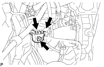
| 4. INSTALL EXHAUST GAS TEMPERATURE SENSOR (LOWER) |
Temporarily install the exhaust gas temperature sensor (lower) with the 2 nuts.
Tighten the 2 nuts.
- Torque:
- 6.4 N*m{ 65 kgf*cm, 57 in.*lbf}
Using SST, tighten the nut of the exhaust gas temperature sensor (lower).
- SST
- 09023-38401
- Torque:
- 30 N*m{ 306 kgf*cm, 22 ft.*lbf}
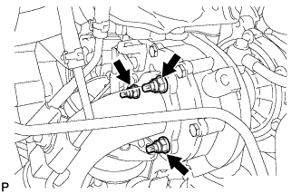
| 5. INSTALL EXHAUST GAS TEMPERATURE SENSOR (UPPER) |
Temporarily install the exhaust gas temperature sensor (upper).
Tighten the 3 nuts.
- Torque:
- 6.4 N*m{ 65 kgf*cm, 57 in.*lbf}
Using SST, tighten the nut of the exhaust gas temperature sensor (upper).
- SST
- 09023-38401
- Torque:
- 30 N*m{ 306 kgf*cm, 22 ft.*lbf}
- HINT:
- Use a torque wrench with a fulcrum length of 30 cm (11.81 in.).
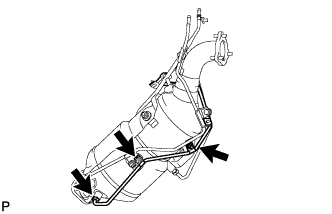
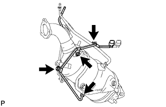
| 6. INSTALL EXHAUST MANIFOLD CONVERTER SUB-ASSEMBLY |
Temporarily install the No. 1 manifold stay.
Temporarily install a new turbine outlet elbow gasket and exhaust manifold converter with the 3 nuts.
Temporarily install the 2 bolts and nut.
Tighten the 3 nuts (Pushing the manifold converter against the No. 1 manifold stay).
- Torque:
- 25 N*m{ 255 kgf*cm, 18 ft.*lbf}
Tighten the 2 bolts and nut.
- Torque:
- 56 N*m{ 571 kgf*cm, 41 ft.*lbf}
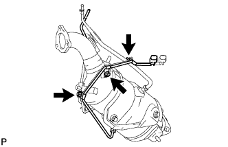
Temporarily install the No. 2 exhaust manifold stay with the 2 bolts and nut.
Tighten the 2 bolts (Pushing the No. 2 exhaust manifold stay against the manual transmission).
- Torque:
- 56 N*m{ 571 kgf*cm, 41 ft.*lbf}
Tighten the nut.
- Torque:
- 56 N*m{ 571 kgf*cm, 41 ft.*lbf}
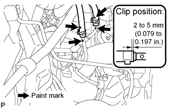
Using pliers, slide the clip to install the No. 1 and No. 2 vacuum transmitting hose assembly.
- HINT:
- Make sure that the paint marks on the No. 1 and No. 2 vacuum transmitting hose assemblies and No. 1 and No. 2 vacuum pipes are aligned.
| 7. INSTALL FRONT EXHAUST PIPE ASSEMBLY |
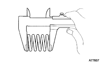
Using vernier calipers, measure the free length of the compression springs.
- Minimum length:
- 38.5 mm (1.516 in.)
If the free length is less than the minimum, replace the compression spring.
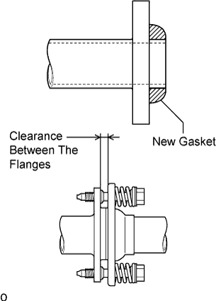
Fully insert 2 new gaskets to the exhaust manifold converter and front exhaust pipe assembly by hand.
- NOTICE:
- HINT:
- Using a plastic hammer, uniformly strike the gasket so that the gasket and front exhaust pipe are properly fit.
Install the front exhaust pipe assembly.
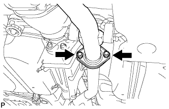
Install the 2 bolts and 2 compression springs.
- Torque:
- 43 N*m{ 439 kgf*cm, 32 ft.*lbf}
- NOTICE:
- After installation, check that the clearance is almost the same at any point between the flanges of the tail exhaust pipe assembly and front exhaust pipe assembly.
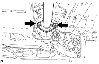
Install the 2 bolts and 2 compression springs.
- Torque:
- 43 N*m{ 439 kgf*cm, 32 ft.*lbf}
- NOTICE:
- After installation, check that the clearance is almost the same at any point between the flanges of the exhaust manifold converter and front exhaust pipe assembly.
| 8. INSTALL BATTERY TRAY |
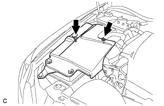
| 9. INSTALL POWER STEERING ECU ASSEMBLY |
- HINT:
| 10. INSTALL ENGINE ROOM SIDE COVER RH |
Install the side cover with the 2 clips.
| 11. INSTALL COOL AIR INTAKE DUCT SEAL |

Install the intake duct seal with the 11 clips.
| 12. INSTALL NO. 1 ENGINE COVER |
Install the No. 1 engine cover.
| 13. PERFORM INITIALIZATION |
- HINT: