Fuel Injector Circuit 2ZR-FXE
Fuel Injector Circuit
Description
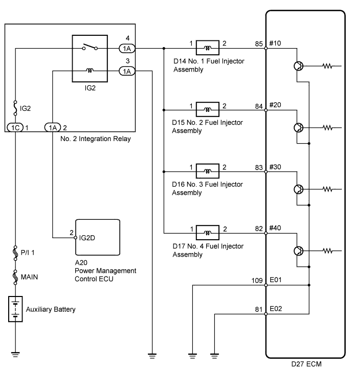
Wiring diagram
Inspection procedure
Check fuel injector assembly (power source voltage)
Inspect fuel injector assembly
Check harness and connector (fuel injector assembly - ecm)
Check harness and connector (no. 2 integration relay (ig2 relay) - fuel injector assembly)
Description
The fuel injectors are located on the intake manifold. They inject fuel into the cylinders based on the signals from the ECM.
Wiring diagram
Inspection procedure
| 1.CHECK FUEL INJECTOR ASSEMBLY (POWER SOURCE VOLTAGE) |
-
Disconnect the fuel injector assembly connectors.
-
Turn the power switch on (IG).
-
Measure the voltage according to the value(s) in the table below.
Standard Voltage:
| Tester Connection |
Switch Condition |
Specified Condition |
| D14-1 - Body ground |
Power switch on (IG) |
11 to 14 V |
| D15-1 - Body ground |
Power switch on (IG) |
11 to 14 V |
| D16-1 - Body ground |
Power switch on (IG) |
11 to 14 V |
| D17-1 - Body ground |
Power switch on (IG) |
11 to 14 V |
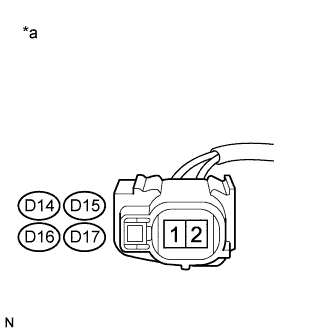
Text in Illustration
| *a |
Front view of wire harness connector (to Fuel Injector Assembly) |
| 2.INSPECT FUEL INJECTOR ASSEMBLY |
-
Inspect the fuel injector assembly .
|
|
| REPLACE FUEL INJECTOR ASSEMBLY |
|
| |
| 3.CHECK HARNESS AND CONNECTOR (FUEL INJECTOR ASSEMBLY - ECM) |
-
Disconnect the fuel injector assembly connectors.
-
Disconnect the ECM connector.
-
Measure the resistance according to the value(s) in the table below.
Standard Resistance:
| Tester Connection |
Condition |
Specified Condition |
| D14-2 - D27-85 (#10) |
Always |
Below 1 ? |
| D15-2 - D27-84 (#20) |
Always |
Below 1 ? |
| D16-2 - D27-83 (#30) |
Always |
Below 1 ? |
| D17-2 - D27-82 (#40) |
Always |
Below 1 ? |
| D14-2 or D27-85 (#10) - Body ground |
Always |
10 ? or higher |
| D15-2 or D27-84 (#20) - Body ground |
Always |
10 ? or higher |
| D16-2 or D27-83 (#30) - Body ground |
Always |
10 ? or higher |
| D17-2 or D27-82 (#40) - Body ground |
Always |
10 ? or higher |
|
|
| REPAIR OR REPLACE HARNESS OR CONNECTOR |
|
| |
| OK |
|
| |
|
| PROCEED TO NEXT SUSPECTED AREA SHOWN IN PROBLEM SYMPTOMS TABLE |
|
| 4.CHECK HARNESS AND CONNECTOR (NO. 2 INTEGRATION RELAY (IG2 RELAY) - FUEL INJECTOR ASSEMBLY) |
-
Disconnect the fuel injector assembly connectors.
-
Remove the No. 2 integration relay from the engine room relay block.
-
Disconnect the No. 2 integration relay connector.
-
Measure the resistance according to the value(s) in the table below.
Standard Resistance:
| Tester Connection |
Condition |
Specified Condition |
| D14-1 - 1A-4 |
Always |
Below 1 ? |
| D15-1 - 1A-4 |
Always |
Below 1 ? |
| D16-1 - 1A-4 |
Always |
Below 1 ? |
| D17-1 - 1A-4 |
Always |
Below 1 ? |
| D14-1 or 1A-4 - Body ground |
Always |
10 k? or higher |
| D15-1 or 1A-4 - Body ground |
Always |
10 k? or higher |
| D16-1 or 1A-4 - Body ground |
Always |
10 k? or higher |
| D17-1 or 1A-4 - Body ground |
Always |
10 k? or higher |
|
|
| REPAIR OR REPLACE HARNESS OR CONNECTOR |
|
| |
| OK |
|
| |
|
| CHECK ECM POWER SOURCE CIRCUIT |
|