Dtc C1622 Open Or Short Circuit In Back Camera Signal
DESCRIPTION
WIRING DIAGRAM
INSPECTION PROCEDURE
CHECK FOR DTC
CHECK HARNESS AND CONNECTOR (RADIO AND DISPLAY RECEIVER ASSEMBLY - REAR TELEVISION CAMERA ASSEMBLY)
CHECK RADIO AND DISPLAY RECEIVER ASSEMBLY
CHECK REAR TELEVISION CAMERA ASSEMBLY
REPLACE REAR TELEVISION CAMERA ASSEMBLY
CHECK FOR DTC
DTC C1622 Open or Short Circuit in Back Camera Signal |
DESCRIPTION
This DTC is stored if the radio and display receiver assembly judges as a result of its self check that the signals or signal lines between the radio and display receiver assembly and the rear television camera assembly are not normal.DTC Code
| DTC Detection Condition
| Trouble Area
|
C1622
| An open or short in the rear television camera signal circuit
| - Harness or connector
- Rear television camera assembly
- Radio and display receiver assembly
|
WIRING DIAGRAM
INSPECTION PROCEDURE
- NOTICE:
- When replacing the radio and display receiver assembly, it is necessary to perform the vehicle contract setting for Connected Service (Click here).
Clear the DTCs (Click here).
Check for DTCs (Click here).
ResultResult
| Proceed to
|
DTC C1622 is not output
| A
|
DTC C1622 is output
| B
|
| 2.CHECK HARNESS AND CONNECTOR (RADIO AND DISPLAY RECEIVER ASSEMBLY - REAR TELEVISION CAMERA ASSEMBLY) |
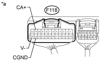
Disconnect the F118 radio and display receiver assembly connector.
Disconnect the S31 rear television camera assembly connector.
Measure the resistance according to the value(s) in the table below.
- Standard Resistance:
Tester Connection
| Condition
| Specified Condition
|
F118-11 (CA+) - S31-6 (CB+)
| Always
| Below 1 Ω
|
F118-12 (V+) - S31-3 (CV+)
| Always
| Below 1 Ω
|
F118-24 (V-) - S31-2 (CV-)
| Always
| Below 1 Ω
|
F118-23 (CGND) - S31-5 (CGND)
| Always
| Below 1 Ω
|
F118-11 (CA+) or S31-6 (CB+) - Body ground
| Always
| 10 kΩ or higher
|
F118-12 (V+) or S31-3 (CV+) - Body ground
| Always
| 10 kΩ or higher
|
F118-24 (V-) or S31-2 (CV-) - Body gound
| Always
| 10 kΩ or higher
|
F118-23 (CGND) or S31-5 (CGND) - Body ground
| Always
| 10 kΩ or higher
|
| | REPAIR OR REPLACE HARNESS OR CONNECTOR |
|
|
| 3.CHECK RADIO AND DISPLAY RECEIVER ASSEMBLY |
Remove the radio and display receiver assembly with the connector still connected (Click here).
Measure the resistance according to the value(s) in the table below.
- Standard Resistance:
Tester Connection
| Condition
| Specified Condition
|
F118-23 (CGND) - Body ground
| Always
| Below 1 Ω
|
F118-24 (V-) - Body ground
| Always
| Below 1 Ω
|
Measure the voltage according to the value(s) in the table below.
- Standard Voltage:
Tester Connection
| Switch Condition
| Specified Condition
|
F118-11 (CA+) - Body ground
| Engine switch on (ACC)
| 5.5 to 7.05 V
|
Text in Illustration*a
| Component with harness connected
(Radio and Display Receiver Assembly)
|
| | REPLACE RADIO AND DISPLAY RECEIVER ASSEMBLY (Click here) |
|
|
| 4.CHECK REAR TELEVISION CAMERA ASSEMBLY |
Remove the radio receiver assembly with the connector still connected (Click here).
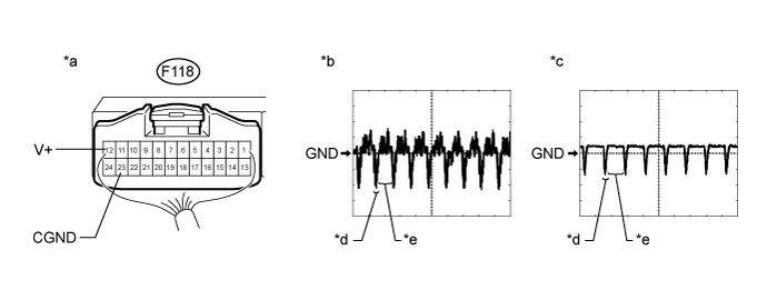
Text in Illustration*a
| Component with harness connected
(Radio and Display Receiver Assembly)
| *b
| Waveform 1
|
*c
| Waveform 2
| *d
| Synchronization Signal
|
*e
| Video Waveform
| -
| -
|
- HINT:
- The video waveform changes according to the image sent by the rear television camera assembly.
Item
| Content
|
Terminal No. (Symbol)
| F118-12 (V+) - F118-23 (CGND)
|
Tool Setting
| 200 mV/DIV., 50 μsec./DIV.
|
Condition
| - Waveform 1: Engine switch on (IG), shift lever in R, camera lens not covered, displaying an image
- Waveform 2: Engine switch on (IG), shift lever in R, camera lens covered, blacking out screen
|
- OK:
- Waveform is as shown in the illustration.
| OK |
|
|
|
| REPLACE RADIO AND DISPLAY RECEIVER ASSEMBLY (Click here) |
|
| 5.REPLACE REAR TELEVISION CAMERA ASSEMBLY |
Replace the rear television camera assembly with a new or normally functioning one (Click here).
Clear the DTCs (Click here).
Check for DTCs (Click here).
ResultResult
| Proceed to
|
DTC C1622 is not output
| A
|
DTC C1622 is output
| B
|
| | REPLACE RADIO AND DISPLAY RECEIVER ASSEMBLY (Click here) |
|
|
| A |
|
|
|
| END (REAR TELEVISION CAMERA ASSEMBLY IS DEFECTIVE) |
|