Multi-Terrain Monitor System Ecu Power Source Circuit
DESCRIPTION
WIRING DIAGRAM
INSPECTION PROCEDURE
CHECK HARNESS AND CONNECTOR (PARKING ASSIST ECU - BATTERY AND BODY GROUND)
MULTI-TERRAIN MONITOR SYSTEM - ECU Power Source Circuit |
DESCRIPTION
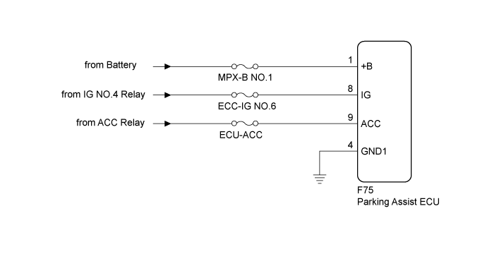
This circuit provides power to operate the parking assist ECU.
WIRING DIAGRAM
INSPECTION PROCEDURE
- NOTICE:
- When "!" mark is displayed on the multi-display after the cable is disconnected from the negative (-) battery terminal, correct the steering angle neutral point (Click here).
- Depending on the parts that are replaced or operations that are performed during vehicle inspection or maintenance, calibration of other systems as well as the multi-terrain monitor system may be needed (Click here).
- Inspect the fuses for circuits related to this system before performing the following inspection procedure.
| 1.CHECK HARNESS AND CONNECTOR (PARKING ASSIST ECU - BATTERY AND BODY GROUND) |
Disconnect the parking assist ECU connector.
Measure the resistance according to the value(s) in the table below.
- Standard Resistance:
Tester Connection
| Condition
| Specified Condition
|
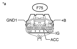
F75-4 (GND1) - Body ground
| Always
| Below 1 Ω
|
Measure the voltage according to the value(s) in the table below.
- Standard Voltage:
Tester Connection
| Condition
| Specified Condition
|
F75-1 (+B) - Body ground
| Always
| 11 to 14 V
|
F75-8 (IG) - Body ground
| Engine switch on (IG)
| 11 to 14 V
|
F75-9 (ACC) - Body ground
| Engine switch on (ACC)
| 11 to 14 V
|
Text in Illustration*a
| Rear view of wire harness connector
(to Parking Assist ECU)
|
| | REPAIR OR REPLACE HARNESS OR CONNECTOR |
|
|
| OK |
|
|
|
| PROCEED TO NEXT SUSPECTED AREA SHOWN IN PROBLEM SYMPTOMS TABLE (Click here) |
|