Dtc P17Aa Transfer Shift Motor Control Circuit High
Drivetrain. Land Cruiser. Urj200, 202 Grj200 Vdj200
DESCRIPTION
WIRING DIAGRAM
INSPECTION PROCEDURE
CHECK ACTUATOR ASSEMBLY (TRANSFER SHIFT MOTOR OR LOCK SHIFT MOTOR)
CHECK HARNESS AND CONNECTOR (4 WHEEL DRIVE CONTROL ECU
AND TRANSFER SHIFT ACTUATOR ASSEMBLY - BODY GROUND)
CHECK HARNESS AND CONNECTOR (4 WHEEL DRIVE CONTROL ECU
AND TRANSFER SHIFT ACTUATOR ASSEMBLY - BODY GROUND)
CHECK HARNESS AND CONNECTOR (4 WHEEL DRIVE CONTROL ECU AND DIFFERENTIAL LOCK SHIFT ACTUATOR - BODY GROUND)
DTC P17AA Transfer Shift Motor Control Circuit High |
DESCRIPTION
This DTC is output when a short to B+ in the high-low transfer shift motor, center differential lock shift motor and differential lock shift motor* drive circuit is detected.- *: w/ Rear Differential Lock
DTC No.
| DTC Detection Condition
- Diagnosis Condition
- Malfunction Status
- Malfunction Time
- Other
| Trouble Area
|
P17AA
| - While the ignition switch is turned to ON or directly after the ignition switch is turned to ON (high-low transfer shift motor, center differential lock shift motor and differential lock shift motor* not operating)
- Short to B+ in the high-low transfer shift motor, center differential lock shift motor and differential lock shift motor* drive circuits
- 0.5 seconds or more (if directly after ignition switch is turned ON, 0.05 seconds)
- 1 trip detection logic
| - Wire harness and connector
- 4 wheel drive control ECU
- Transfer shift actuator assembly
- Differential lock shift actuator*
|
- *: w/ Rear Differential Lock
WIRING DIAGRAM
Refer to DTC P17A9 (Click here).
INSPECTION PROCEDURE
| 1.CHECK ACTUATOR ASSEMBLY (TRANSFER SHIFT MOTOR OR LOCK SHIFT MOTOR) |
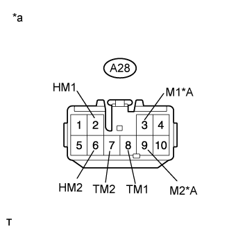
Disconnect the A28 4 wheel drive control ECU connector.
|
Measure the voltage according to the value(s) in the table below
- Standard Voltage:
Transfer Shift Actuator Assembly (High-low Transfer Shift Motor) SideTester Connection
| Condition
| Specified Condition
|
A28-2 (HM1) or A28-6 (HM2) - Body ground
| Ignition switch ON
| Below 1 V
|
Transfer Shift Actuator Assembly (Center Differential Lock Shift Motor) SideTester Connection
| Condition
| Specified Condition
|
A28-8 (TM1) or A28-7 (TM2) - Body ground
| Ignition switch ON
| Below 1 V
|
Differential Lock Shift Actuator (Differential Lock Shift Motor) Side (w/ Rear Differential Lock)Tester Connection
| Condition
| Specified Condition
|
A28-3 (M1) or A28-9 (M2) - Body ground
| Ignition switch ON
| Below 1 V
|
Text in Illustration*A
| w/ Rear Differential Lock
|
*a
| Front view of wire harness connector
(to 4 Wheel Drive Control ECU)
|
- Result:
Result
| Proceed to
|
OK
| for LHD
| A
|
for RHD
| B
|
NG (transfer shift actuator assembly (high-low transfer shift motor) side)
| C
|
NG (transfer shift actuator assembly (center differential lock shift motor) side)
| D
|
NG (differential lock shift actuator (differential lock shift motor) side (w/ Rear Differential Lock))
| E
|
| 2.CHECK HARNESS AND CONNECTOR (4 WHEEL DRIVE CONTROL ECU
AND TRANSFER SHIFT ACTUATOR ASSEMBLY - BODY GROUND) |
Disconnect the A28 4 wheel drive control ECU connector.
Disconnect the C38 transfer shift actuator assembly connector.
Measure the voltage according to the value(s) in the table below.
- Standard Voltage:
Tester Connection
| Condition
| Specified Condition
|
A28-2 (HM1) or C38-1 (HM1) - Body ground
| Ignition switch ON
| Below 1 V
|
A28-6 (HM2) or C38-2 (HM2) - Body ground
| Ignition switch ON
| Below 1 V
|
| | REPAIR OR REPLACE HARNESS OR CONNECTOR |
|
|
| OK |
|
|
|
| REPLACE TRANSFER SHIFT ACTUATOR ASSEMBLY (Click here) |
|
| 3.CHECK HARNESS AND CONNECTOR (4 WHEEL DRIVE CONTROL ECU
AND TRANSFER SHIFT ACTUATOR ASSEMBLY - BODY GROUND) |
Disconnect the A28 4 wheel drive control ECU connector.
Disconnect the C37 transfer shift actuator assembly connector.
Measure the voltage according to the value(s) in the table below.
- Standard Voltage:
Tester Connection
| Condition
| Specified Condition
|
A28-8 (TM1) or C37-1 (TM1) - Body ground
| Ignition switch ON
| Below 1 V
|
A28-7 (TM2) or C37-2 (TM1) - Body ground
| Ignition switch ON
| Below 1 V
|
| | REPAIR OR REPLACE HARNESS OR CONNECTOR |
|
|
| OK |
|
|
|
| REPLACE TRANSFER SHIFT ACTUATOR ASSEMBLY (Click here) |
|
| 4.CHECK HARNESS AND CONNECTOR (4 WHEEL DRIVE CONTROL ECU AND DIFFERENTIAL LOCK SHIFT ACTUATOR - BODY GROUND) |
Disconnect the A28 4 wheel drive control ECU connector.
Disconnect the f1 differential lock shift actuator connector.
Measure the voltage according to the value(s) in the table below.
- Standard Voltage:
Tester Connection
| Condition
| Specified Condition
|
A28-3 (M1) or f1-3 - Body ground
| Ignition switch ON
| Below 1 V
|
A28-9 (M2) or f1-2 - Body ground
| Ignition switch ON
| Below 1 V
|
| | REPAIR OR REPLACE HARNESS OR CONNECTOR |
|
|
| OK |
|
|
|
| REPLACE DIFFERENTIAL LOCK SHIFT ACTUATOR (Click here) |
|