Dtc P0812 Reverse Input Circuit
Drivetrain. Land Cruiser. Urj200, 202 Grj200 Vdj200
DESCRIPTION
MONITOR DESCRIPTION
WIRING DIAGRAM
INSPECTION PROCEDURE
CHECK PARK/NEUTRAL POSITION SWITCH ASSEMBLY (POWER SOURCE)
INSPECT PARK/NEUTRAL POSITION SWITCH ASSEMBLY
CHECK HARNESS AND CONNECTOR (PARK/NEUTRAL POSITION SWITCH ASSEMBLY - TCM)
DTC P0812 Reverse Input Circuit |
DESCRIPTION
The park/neutral position switch detects the shift lever position and sends signals to the TCM.DTC No.
| DTC Detection Condition
- Diagnosis Condition
- Malfunction Status
- Malfunction Time
- Other
| Trouble Area
|
P0812
| - Battery voltage is 9.5 V or higher, shift lever in R and DTC P0705 is not detected
- R terminal voltage is low
- 5 times
- 1-trip detection logic
| - Open or short in park/neutral position switch assembly circuit
- Park/neutral position switch assembly
- TCM
|
- Battery voltage is 9.5 V or higher, shift lever in D and DTC P0705 is not detected
- R terminal voltage is high
- 5 times
- 1-trip detection logic
| - Short in park/neutral position switch assembly circuit
- Park/neutral position switch assembly
- TCM
|
MONITOR DESCRIPTION
This DTC indicates a problem the park/neutral position switch assembly or the wire harness in the park/neutral position switch assembly circuit.The park/neutral position switch assembly detects the shift lever position and sends signals to the TCM.For safety, the park/neutral position switch assembly detects the shift lever position so that the engine can be started only when the shift lever is in P or N.The park/neutral position switch assembly sends signals to the TCM according to the shift lever position (P, N, R or D).The TCM determines that there is a problem with the switch or related parts if it receives an R position signal when the shift lever is in D or it does not receives an R position signal when the shift lever is in R. The TCM stores the DTC.
WIRING DIAGRAM
Refer to DTC P0705 (Click here).
INSPECTION PROCEDURE
- NOTICE:
- Perform registration and/or initialization when parts related to the automatic transmission are replaced (Click here).
- Inspect the fuses for circuits related to this system before performing the following inspection procedure.
- HINT:
- After performing repair, clear the DTCs and perform the following procedure to check that DTCs are not output.
- Turn the engine switch on (IG).
- Wait for 5 seconds or more with the shift lever in D.
- Wait for 5 seconds or more with the shift lever in R.
- Check for DTCs again (Click here).
| 1.CHECK PARK/NEUTRAL POSITION SWITCH ASSEMBLY (POWER SOURCE) |
Disconnect the park/neutral position switch assembly connector.
Turn the engine switch on (IG).
Measure the voltage according to the value(s) in the table below.
- Standard Voltage:
Tester Connection
| Switch Condition
| Specified Condition
|
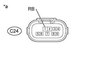
C24-1 (RB) - Body ground
| Engine switch on (IG)
| 11 to 14 V
|
Text in Illustration*a
| Front view of wire harness connector
(to Park/Neutral Position Switch Assembly)
|
| | REPAIR OR REPLACE HARNESS OR CONNECTOR (PARK/NEUTRAL POSITION SWITCH ASSEMBLY - BATTERY) |
|
|
| 2.INSPECT PARK/NEUTRAL POSITION SWITCH ASSEMBLY |
Disconnect the park/neutral position switch assembly connector.
Measure the resistance according to the value(s) in the table below.
- Standard Resistance:
Tester Connection
| Condition
| Specified Condition
|
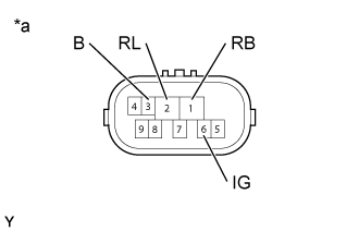
1 (RB) - 2 (RL)
| Shift lever in R
| Below 1 Ω
|
1 (RB) - 2 (RL)
| Shift lever not in R
| 10 kΩ or higher
|
3 (B) - 2 (RL)
| Shift lever in P, R, N, D and S
| 10 kΩ or higher
|
6 (IG) - 2 (RL)
| Shift lever in P, R, N, D and S
| 10 kΩ or higher
|
Text in Illustration*a
| Component without harness connected
(Park/Neutral Position Switch Assembly)
|
| | REPLACE PARK/NEUTRAL POSITION SWITCH ASSEMBLY (Click here) |
|
|
| 3.CHECK HARNESS AND CONNECTOR (PARK/NEUTRAL POSITION SWITCH ASSEMBLY - TCM) |
Disconnect the C24 park/neutral position switch assembly connector.
Disconnect the A82 TCM connector.
Measure the resistance according to the value(s) in the table below.
- Standard Resistance:
Tester Connection
| Condition
| Specified Condition
|
C24-2 (RL) - A82-5 (R)
| Always
| Below 1 Ω
|
C24-2 (RL) or A82-5 (R) - Body ground
| Always
| 10 kΩ or higher
|
| | REPAIR OR REPLACE HARNESS OR CONNECTOR |
|
|