Dtc B1324 Lost Communication With Meter
DESCRIPTION
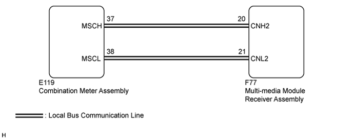
WIRING DIAGRAM
INSPECTION PROCEDURE
CHECK HARNESS AND CONNECTOR (MULTI-MEDIA MODULE RECEIVER ASSEMBLY - COMBINATION METER ASSEMBLY)
INSPECT COMBINATION METER ASSEMBLY
INSPECT MULTI-MEDIA MODULE RECEIVER ASSEMBLY
REPLACE COMBINATION METER ASSEMBLY
CLEAR DTC
CHECK DTC
DTC B1324 Lost Communication with Meter |
DESCRIPTION
This DTC is stored when a communication error occurs between the multi-media module receiver assembly and combination meter assembly.DTC Code
| DTC Detection Condition
| Trouble Area
|
B1324
| After the multi-media module receiver assembly receives a registration information signal, which is sent by the combination meter assembly when the engine switch is on (ACC), 1 or more times, the multi-media module receiver assembly cannot receive the signal for 30 seconds or more.
| - Combination meter assembly
- Multi-media module receiver assembly
- Harness or connector
|
WIRING DIAGRAM
INSPECTION PROCEDURE
- NOTICE:
- Depending on the parts that are replaced during vehicle inspection or maintenance, performing initialization, registration or calibration may be needed. Refer to Precaution for Navigation System (Click here).
- When replacing the combination meter assembly, make sure to replace it with a new one.
| 1.CHECK HARNESS AND CONNECTOR (MULTI-MEDIA MODULE RECEIVER ASSEMBLY - COMBINATION METER ASSEMBLY) |
Disconnect the F77 multi-media module receiver assembly connector.
Disconnect the E119 combination meter assembly connector.
Measure the resistance according to the value(s) in the table below.
- Standard Resistance:
Tester Connection
| Condition
| Specified Condition
|
F77-20 (CNH2) - E119-37 (MSCH)
| Always
| Below 1 Ω
|
F77-21 (CNL2) - E119-38 (MSCL)
| Always
| Below 1 Ω
|
F77-20 (CNH2) - Body ground
| Always
| 10 kΩ or higher
|
F77-21 (CNL2) - Body ground
| Always
| 10 kΩ or higher
|
F77-20 (CNH2) - F77-21 (CNL2)
| Always
| 10 kΩ or higher
|
Measure the voltage according to the value(s) in the table below.
- Standard Voltage:
Tester Connection
| Condition
| Specified Condition
|
F77-20 (CNH2) - Body ground
| Always
| Below 1 V
|
F77-21 (CNL2) - Body ground
| Always
| Below 1 V
|
| | REPAIR OR REPLACE HARNESS OR CONNECTOR |
|
|
| 2.INSPECT COMBINATION METER ASSEMBLY |
Remove the combination meter assembly (Click here).
Measure the resistance according to the value(s) in the table below.
- Standard Resistance:
Tester Connection
| Condition
| Specified Condition
|
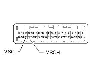
37 (MSCH) - 38 (MSCL)
| Always
| 108 to 132 Ω
|
| 3.INSPECT MULTI-MEDIA MODULE RECEIVER ASSEMBLY |
Remove the multi-media module receiver assembly (Click here).
Measure the resistance according to the value(s) in the table below.
- Standard Resistance:
Tester Connection
| Condition
| Specified Condition
|
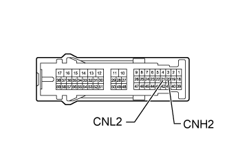
20 (CNH2) - 21 (CNL2)
| Always
| 108 to 132 Ω
|
| | REPLACE MULTI-MEDIA MODULE RECEIVER ASSEMBLY (Click here) |
|
|
| 4.REPLACE COMBINATION METER ASSEMBLY |
Replace the combination meter assembly (Click here).
Clear the DTCs (Click here).
Recheck for DTCs and check if the same DTCs are output again (Click here).
- OK:
- No DTCs are output.
| | REPLACE MULTI-MEDIA MODULE RECEIVER ASSEMBLY (Click here) |
|
|
| OK |
|
|
|
| END (COMBINATION METER ASSEMBLY IS DEFECTIVE) |
|