Dtc B1577 Gvif Disconnected (From Emv/Mm Integrated Device To Rse)
DESCRIPTION
WIRING DIAGRAM
INSPECTION PROCEDURE
CLEAR DTC
CHECK FOR DTC
CHECK HARNESS AND CONNECTOR (GVIF CABLE)
CHECK HARNESS AND CONNECTOR (GVIF CABLE)
REPLACE MULTI-DISPLAY CONTROLLER SUB-ASSEMBLY
CLEAR DTC
CHECK FOR DTC
DTC B1577 GVIF Disconnected (from EMV/MM Integrated Device to RSE) |
DESCRIPTION
The multi-media module receiver assembly and multi-display controller sub-assembly are connected by GVIF cable.When a GVIF cable error occurs between the multi-media module receiver assembly and multi-display controller sub-assembly, this DTCs will be stored.DTC Code
| DTC Detection Condition
| Trouble Area
|
B1577
| GVIF disconnected (from multi-media module receiver assembly to multi-display controller sub-assembly)
| - Harness and connector (GVIF cable)
- Multi-display controller sub-assembly
- Multi-media module receiver assembly
|
WIRING DIAGRAM
INSPECTION PROCEDURE
Clear the DTCs (Click here).
Recheck for DTCs and check if the same DTC is output again (Click here).
- OK:
- No DTCs are output.
| 3.CHECK HARNESS AND CONNECTOR (GVIF CABLE) |
Check if the GVIF cable connectors between the multi-media module receiver assembly and the multi-display controller sub-assembly have any connection problems (Click here).
- OK:
- There are no connection problems.
| | REMOVE CONNECTION PROBLEMS (GVIF CABLE) |
|
|
| 4.CHECK HARNESS AND CONNECTOR (GVIF CABLE) |
Remove the GVIF cable from the multi-media module receiver assembly and multi-display controller sub-assembly.
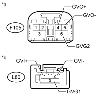
Measure the resistance according to the value(s) in the table below.
- Standard Resistance:
Tester Connection
| Condition
| Specified Condition
|
F105-4 (GVO+) - L80-1 (GVI+)
| Always
| Below 1 Ω
|
F105-5 (GVO-) - L80-2 (GVI-)
| Always
| Below 1 Ω
|
F105-6 (GVG2) - L80-3 (GVG1)
| Always
| Below 1 Ω
|
F105-4 (GVO+) or L80-1 (GVI+) - Body ground
| Always
| 10 kΩ or higher
|
F105-5 (GVO-) or L80-2 (GVI-) - Body ground
| Always
| 10 kΩ or higher
|
F105-6 (GVG2) or L80-3 (GVG1) - Body ground
| Always
| 10 kΩ or higher
|
Text in Illustration*a
| GVIF Cable
(to Multi-media Module Receiver Assembly)
|
*b
| GVIF Cable
(to Multi-display Controller Sub-assembly)
|
| | REPLACE HARNESS AND CONNECTOR (GVIF CABLE) |
|
|
| 5.REPLACE MULTI-DISPLAY CONTROLLER SUB-ASSEMBLY |
Replace the multi-display controller sub-assembly with a new or known good one (Click here).
Clear the DTCs (Click here).
Recheck for DTCs and check if the same DTC is output again (Click here).
- OK:
- No DTCs are output.
| | REPLACE MULTI-MEDIA MODULE RECEIVER ASSEMBLY (Click here) |
|
|
| OK |
|
|
|
| END (MULTI-DISPLAY CONTROLLER SUB-ASSEMBLY IS DEFECTIVE) |
|