Transfer System 4Wd Control Switch Circuit
Drivetrain. Land Cruiser. Urj200, 202 Grj200 Vdj200
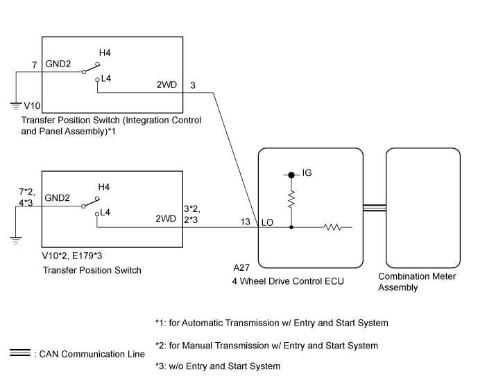
WIRING DIAGRAM
INSPECTION PROCEDURE
CONFIRM PROBLEM SYMPTOM
CHECK 4LO INDICATOR LIGHT
CHECK CAN COMMUNICATION LINE
READ VALUE USING GTS (TRANSFER POSITION SWITCH)
CHECK COMBINATION METER ASSEMBLY (4LO INDICATOR LIGHT)
INSPECT INTEGRATION CONTROL AND PANEL ASSEMBLY OR TRANSFER POSITION SWITCH
CHECK HARNESS AND CONNECTOR (4 WHEEL DRIVE CONTROL ECU - INTEGRATION CONTROL AND PANEL ASSEMBLY OR TRANSFER POSITION SWITCH
CHECK 4LO INDICATOR LIGHT
CHECK CAN COMMUNICATION LINE
READ VALUE USING GTS (4LO INDICATOR LIGHT)
TRANSFER SYSTEM - 4WD Control Switch Circuit |
WIRING DIAGRAM
INSPECTION PROCEDURE
| 1.CONFIRM PROBLEM SYMPTOM |
Confirm the problem symptoms.
ResultResult
| Proceed to
|
The 4LO indicator light remains off after operating the transfer position switch (integration control and panel assembly) to L4*1
The 4LO indicator light remains off after operating the transfer position switch to L4*2, *3
| A
|
The 4LO indicator light remains on after operating the transfer position switch to H4*1
The 4LO indicator light remains on after operating the transfer position switch (integration control and panel assembly) to H4*2, *3
| B
|
- *1: for Automatic Transmission w/ Entry and Start System
- *2: for Manual Transmission w/ Entry and Start System
- *3: w/o Entry and Start System
| 2.CHECK 4LO INDICATOR LIGHT |
- HINT:
- Perform the following procedure with the vehicle stopped.
Turn the ignition switch to ON.
for Automatic Transmission:
Move the shift lever to N.
for Manual Transmission:
Depress the clutch pedal.
for Automatic Transmission w/ Entry and Start System:
Turn the transfer position switch (integration control and panel assembly) to L4.
for Manual Transmission w/ Entry and Start System:
Turn the transfer position switch to L4.
w/o Entry and Start System:
Turn the transfer position switch to L4.
Check the 4LO indicator light.
ResultResult
| Proceed to
|
The 4LO indicator light remains off
| A
|
The 4LO indicator light is blinking or illuminated
| B
|
- Blinking: Blinks at 0.5 second intervals (0.5 seconds on and 0.5 seconds off)
| 3.CHECK CAN COMMUNICATION LINE |
Select "Bus Check" from the System Selection Menu screen, and follow the prompts on the screen to inspect the CAN bus (for LHD with Central Gateway ECU: Click here, for LHD without Central Gateway ECU: Click here, for RHD with Central Gateway ECU: Click here, for RHD without Central Gateway ECU: Click here).
- OK:
- "Bus Check" indicates no malfunctions in CAN communication.
ResultResult
| Proceed to
|
DTC is not output
| A
|
DTC is output
| for LHD with Central Gateway ECU
| B
|
for LHD without Central Gateway ECU
| C
|
for RHD with Central Gateway ECU
| D
|
for RHD without Central Gateway ECU
| E
|
| 4.READ VALUE USING GTS (TRANSFER POSITION SWITCH) |
Turn the ignition switch off.
Connect the GTS to the DLC3.
Turn the GTS on.
Turn the ignition switch to ON.
Enter the following menus: Powertrain / Four Wheel Drive / Data List.
According to the display on the GTS, read the Data List.
Four Wheel DriveTester Display
| Measurement Item/Range
| Normal Condition
| Diagnostic Note
|
Transfer Position Control SW
| Transfer position switch status/
ON or OFF
| ON: L4
OFF: H4
| -
|
- OK:
- for Automatic Transmission w/ Entry and Start System:
Display changes according to transfer position switch (integration control and panel assembly) operation.
for Manual Transmission w/ Entry and Start System:
Display changes according to transfer position switch operation.
w/o Entry and Start System:
Display changes according to transfer position switch operation.
| 5.CHECK COMBINATION METER ASSEMBLY (4LO INDICATOR LIGHT) |
Turn the ignition switch off.
Perform an Active Test of the combination meter assembly using the GTS (Click here).
Check the combination meter assembly.
- OK:
- The 4LO indicator light turns on or off in accordance with the GTS.
- Result:
Result
| Proceed to
|
OK
| for LHD
| A
|
for RHD
| B
|
NG
| C
|
| 6.INSPECT INTEGRATION CONTROL AND PANEL ASSEMBLY OR TRANSFER POSITION SWITCH |
for Automatic Transmission w/ Entry and Start System:
Remove the transfer position switch (integration control and panel assembly) (Click here).
Inspect the transfer position switch (integration control and panel assembly) (Click here).
- OK:
- The transfer position switch (integration control and panel assembly) operates normally.
for Manual Transmission w/ Entry and Start System:
Remove the transfer position switch (Click here).
Inspect the transfer position switch (Click here).
- OK:
- The transfer position switch operates normally.
w/o Entry and Start System:
Remove the transfer position switch (Click here).
Inspect the transfer position switch (Click here).
- OK:
- The transfer position switch operates normally.
- Result:
Result
| Proceed to
|
OK
| A
|
NG
| for Automatic Transmission w/ Entry and Start System
| B
|
for Manual Transmission w/ Entry and Start System
| C
|
w/o Entry and Start System
| D
|
| | REPLACE INTEGRATION CONTROL AND PANEL ASSEMBLY (Click here) |
|
|
| |
|
| |
|
| 7.CHECK HARNESS AND CONNECTOR (4 WHEEL DRIVE CONTROL ECU - INTEGRATION CONTROL AND PANEL ASSEMBLY OR TRANSFER POSITION SWITCH |
Disconnect the A27 4 wheel drive control ECU connector.
for Automatic Transmission w/ Entry and Start System:
Disconnect the V10 transfer position switch (integration control and panel assembly) connector.
for Manual Transmission w/ Entry and Start System:
Disconnect the V10 transfer position switch connector.
w/o Entry and Start System:
Disconnect the E179 transfer position switch connector.
Measure the resistance according to the value(s) in the table below.
- Standard Resistance:
for Automatic Transmission w/ Entry and Start System:Tester Connection
| Condition
| Specified Condition
|
A27-13 (LO) - V10-3 (2WD)
| Always
| Below 1 Ω
|
A27-13 (LO) or V10-3 (2WD) - Body ground
| Always
| 10 kΩ or higher
|
V10-7 (GND2) - Body ground
| Always
| Below 1 Ω
|
for Manual Transmission w/ Entry and Start System:Tester Connection
| Condition
| Specified Condition
|
A27-13 (LO) - V10-3 (2WD)
| Always
| Below 1 Ω
|
A27-13 (LO) or V10-3 (2WD) - Body ground
| Always
| 10 kΩ or higher
|
V10-7 (GND2) - Body ground
| Always
| Below 1 Ω
|
w/o Entry and Start System:Tester Connection
| Condition
| Specified Condition
|
A27-13 (LO) - E179-2 (2WD)
| Always
| Below 1 Ω
|
A27-13 (LO) or E179-2 (2WD) - Body ground
| Always
| 10 kΩ or higher
|
E179-4 (GND2) - Body ground
| Always
| Below 1 Ω
|
- Result:
Result
| Proceed to
|
OK
| for LHD
| A
|
for RHD
| B
|
NG
| C
|
| |
|
| | REPAIR OR REPLACE HARNESS OR CONNECTOR |
|
|
| 8.CHECK 4LO INDICATOR LIGHT |
- HINT:
- Perform the following procedure with the vehicle stopped.
Turn the ignition switch to ON.
for Automatic Transmission:
Move the shift lever to N.
for Manual Transmission:
Depress the clutch pedal.
for Automatic Transmission w/ Entry and Start System:
Turn the transfer position switch (integration control and panel assembly) to H4.
for Manual Transmission w/ Entry and Start System:
Turn the transfer position switch to H4.
w/o Entry and Start System:
Turn the transfer position switch to H4.
Check the 4LO indicator light.
ResultResult
| Proceed to
|
The 4LO indicator light remains illuminated
| A
|
The 4LO indicator light is blinking or illuminated
| B
|
- Blinking: Blinks at 0.5 second intervals (0.5 seconds on and 0.5 seconds off)
| 9.CHECK CAN COMMUNICATION LINE |
Select "Bus Check" from the System Selection Menu screen, and follow the prompts on the screen to inspect the CAN bus (for LHD with Central Gateway ECU: Click here, for LHD without Central Gateway ECU: Click here, for RHD with Central Gateway ECU: Click here, for RHD without Central Gateway ECU: Click here).
- OK:
- "Bus Check" indicates no malfunctions in CAN communication.
ResultResult
| Proceed to
|
DTC is not output
| A
|
DTC is output
| for LHD with Central Gateway ECU
| B
|
for LHD without Central Gateway ECU
| C
|
for RHD with Central Gateway ECU
| D
|
for RHD without Central Gateway ECU
| E
|
| 10.READ VALUE USING GTS (4LO INDICATOR LIGHT) |
Turn the ignition switch off.
Connect the GTS to the DLC3.
Turn the GTS on.
Turn the ignition switch to ON.
Enter the following menus: Powertrain / Four Wheel Drive / Data List.
According to the display on the GTS, read the Data List.
Four Wheel DriveTester Display
| Measurement Item/Range
| Normal Condition
| Diagnostic Note
|
L4 Indicator Request
| 4LO indicator light request/
Blink3, Blink1, ON, OFF
| - Blink3: Indicator light rapidly blinks
- Blink1: Indicator light blinks
- ON: Indicator light illuminates
- OFF: Indicator light turns off
| - Blinking: 0.5 second intervals (0.5 seconds on and 0.5 seconds off)
- Rapidly blinking: 0.25 second intervals (0.25 seconds on and 0.25 seconds off)
|
for Automatic Transmission w/ Entry and Start System:
Operate the transfer position switch (integration control and panel assembly) several times between H4 and L4, and then check the Techstream display condition of the 4LO indicator light.
for Manual Transmission w/ Entry and Start System:
Operate the transfer position switch several times between H4 and L4, and then check the Techstream display condition of the 4LO indicator light.
w/o Entry and Start System:
Operate the transfer position switch several times between H4 and L4, and then check the Techstream display condition of the 4LO indicator light.
- Result:
Result
| Proceed to
|
Data List continues to display ON even when transfer position switch (integration control and panel assembly) is operated*1
Data List continues to display ON even when transfer position switch is operated*2, *3
| for LHD
| A
|
for RHD
| B
|
Data List display changes according to transfer position switch (integration control and panel assembly) operation*1
Data List display changes according to transfer position switch operation*2, *3
| C
|
- *1: for Automatic Transmission w/ Entry and Start System
- *2: for Manual Transmission w/ Entry and Start System
- *3: w/o Entry and Start System