Dtc B1574 Gvif Disconnected (From Park Assist/Monitoring Ecu To Emv/Mm Integrated Device)
DESCRIPTION
WIRING DIAGRAM
INSPECTION PROCEDURE
CLEAR DTC
CHECK DTC
CHECK HARNESS AND CONNECTOR (GVIF CABLE)
REPLACE HARNESS AND CONNECTOR (GVIF CABLE)
DTC B1574 GVIF Disconnected (from Park Assist/Monitoring ECU to EMV/MM Integrated Device) |
DESCRIPTION
DTC Code
| DTC Detection Condition
| Trouble Area
|
B1574
| GVIF disconnected (from Parking assist ECU to Multi-display)
| - Harness or connector (GVIF cable)
- Multi-display assembly
|
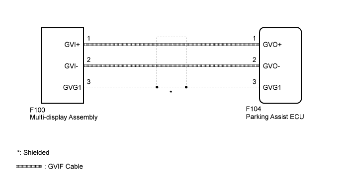
WIRING DIAGRAM
INSPECTION PROCEDURE
Clear the DTCs (Click here).
Recheck for DTCs and check if the same DTC is output again (Click here).
- OK:
- No DTCs are output.
| 3.CHECK HARNESS AND CONNECTOR (GVIF CABLE) |
Check that the digital signal lines between the multi-display assembly and parking assist ECU are not sharply bent or pinched, and that the connectors are properly connected and there are no other installation problems.
- OK:
- There are no installation problems.
| | REPLACE HARNESS AND CONNECTOR (GVIF CABLE) |
|
|
| 4.REPLACE HARNESS AND CONNECTOR (GVIF CABLE) |
Disconnect the F100 multi-display assembly connector.
Disconnect the F104 parking assist ECU connector.
Measure the resistance according to the value(s) in the table below.
- Standard Resistance:
Tester Connection
| Condition
| Specified Condition
|
F100-1 (GVI+) - F104-1 (GVO+)
| Always
| Below 1 Ω
|
F100-2 (GVI-) - F104-2 (GVO-)
| Always
| Below 1 Ω
|
F100-3 (GVG1) - F104-3 (GVG1)
| Always
| Below 1 Ω
|
F100-1 (GVI+) - Body ground
| Always
| 10 kΩ or higher
|
F100-2 (GVI-) - Body ground
| Always
| 10 kΩ or higher
|
F100-3 (GVG1) - Body ground
| Always
| 10 kΩ or higher
|
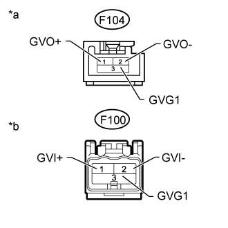
Text in Illustration*a
| Front view of wire harness connector
(to Parking Assist ECU)
|
*b
| Front view of wire harness connector
(to Multi-display Assembly)
|
| | REPLACE HARNESS AND CONNECTOR (GVIF CABLE) |
|
|