Navigation System Parking Brake Switch Circuit
DESCRIPTION
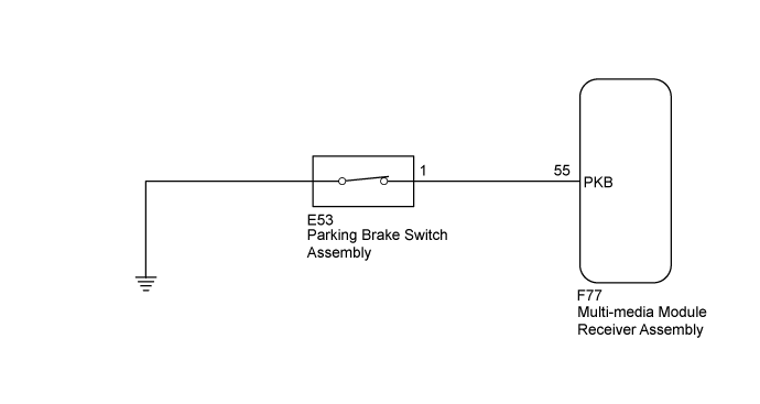
WIRING DIAGRAM
INSPECTION PROCEDURE
CHECK VEHICLE SIGNAL (OPERATION CHECK)
CHECK HARNESS AND CONNECTOR (MULTI-MEDIA MODULE RECEIVER ASSEMBLY - PARKING BRAKE SWITCH ASSEMBLY)
INSPECT PARKING BRAKE SWITCH ASSEMBLY
NAVIGATION SYSTEM - Parking Brake Switch Circuit |
DESCRIPTION
This circuit includes the parking brake switch assembly and multi-media module receiver assembly.
WIRING DIAGRAM
INSPECTION PROCEDURE
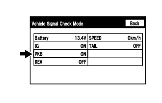
| 1.CHECK VEHICLE SIGNAL (OPERATION CHECK) |
Display the "Vehicle Signal Check Mode" screen (Click here).
Check that the display changes between ON and OFF according to the parking brake operation.
- OK:
Parking Brake Condition
| Display
|
Applied
| ON
|
Released
| OFF
|
- HINT:
- This display is updated once per second. As a result, it is normal for the display to lag behind the actual parking brake operation.
| OK |
|
|
|
| PROCEED TO NEXT SUSPECTED AREA SHOWN IN PROBLEM SYMPTOMS TABLE (Click here) |
|
| 2.CHECK HARNESS AND CONNECTOR (MULTI-MEDIA MODULE RECEIVER ASSEMBLY - PARKING BRAKE SWITCH ASSEMBLY) |
Disconnect the F77 multi-media module receiver assembly connector.
Disconnect the E53 parking brake switch assembly connector.
Measure the resistance according to the value(s) in the table below.
- Standard Resistance:
Tester Connection
| Condition
| Specified Condition
|
F77-55 (PKB) - E53-1
| Always
| Below 1 Ω
|
F77-55 (PKB) - Body ground
| Always
| 10 kΩ or higher
|
| | REPAIR OR REPLACE HARNESS OR CONNECTOR |
|
|
| 3.INSPECT PARKING BRAKE SWITCH ASSEMBLY |
Remove the parking brake switch assembly. (Click here).
Measure the resistance according to the value(s) in the table below.
- Standard Resistance:
Tester Connection
| Switch Condition
| Specified Condition
|
1 - Switch body
| ON (Shaft not pressed)
| Below 1 Ω
|
OFF (Shaft pressed)
| 10 kΩ or higher
|
Text in Illustration
| ON
|

| OFF
|
| | REPLACE PARKING BRAKE SWITCH ASSEMBLY (Click here) |
|
|
| OK |
|
|
|
| PROCEED TO NEXT SUSPECTED AREA SHOWN IN PROBLEM SYMPTOMS TABLE (Click here) |
|