Dtc C1379 Downhill Assist Control Switch Malfunction (Test Mode Dtc)
Brake. Land Cruiser. Urj200, 202 Grj200 Vdj200
DESCRIPTION
WIRING DIAGRAM
INSPECTION PROCEDURE
INSPECT SUSPENSION CONTROL SWITCH OR INTEGRATION CONTROL AND PANEL ASSEMBLY
CHECK HARNESS AND CONNECTOR (SKID CONTROL ECU - SUSPENSION CONTROL SWITCH OR INTEGRATION CONTROL AND PANEL ASSEMBLY)
CHECK TEST MODE DTC
DTC C1379 Downhill Assist Control Switch Malfunction (Test Mode DTC) |
DESCRIPTION
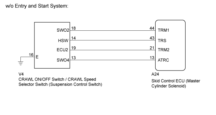
- w/o Entry and Start System
DTC C1379 is cleared when the CRAWL ON/OFF switch / CRAWL speed selector switch (suspension control switch) sends a CRAWL ON/OFF switch / CRAWL speed selector switch (suspension control switch) operation signal or when test mode ends.
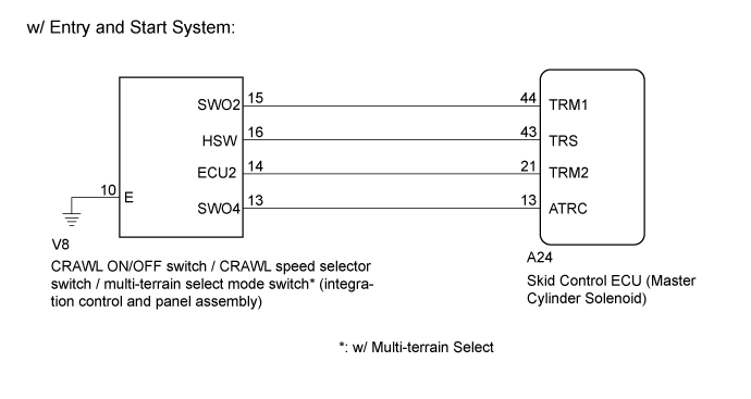
- w/ Entry and Start System
DTC C1379 is cleared when the CRAWL ON/OFF switch / CRAWL speed selector switch / multi-terrain select mode switch* (integration control and panel assembly) sends a CRAWL ON/OFF switch / CRAWL speed selector switch / multi-terrain select mode switch* (integration control and panel assembly) operation signal or when test mode ends.
*: w/ Multi-terrain Select
DTC Code
| DTC Detection Condition
| Trouble Area
|
C1379
| Stored only during test mode.
| - CRAWL ON/OFF switch / CRAWL speed selector switch (Suspension control switch)*1
- CRAWL ON/OFF switch / CRAWL speed selector switch / multi-terrain select mode switch*2 (integration control and panel assembly)*3
- Harness or connector
- Skid control ECU (Master cylinder solenoid)
|
- *1: w/o Entry and Start System
- *2: w/ Multi-terrain Select
- *3: w/ Entry and Start System
WIRING DIAGRAM
INSPECTION PROCEDURE
- NOTICE:
- After replacing the master cylinder solenoid, perform zero point calibration and store the system information (Click here).
| 1.INSPECT SUSPENSION CONTROL SWITCH OR INTEGRATION CONTROL AND PANEL ASSEMBLY |
w/o Entry and Start System:
Remove the CRAWL ON/OFF switch / CRAWL speed selector switch (suspension control switch) (Click here).
Inspect the CRAWL ON/OFF switch / CRAWL speed selector switch (suspension control switch) (Click here).
w/ Entry and Start System:
Remove the CRAWL ON/OFF switch / CRAWL speed selector switch / multi-terrain select mode switch* (integration control and panel assembly) (Click here).
Inspect the CRAWL ON/OFF switch / CRAWL speed selector switch / multi-terrain select mode switch* (integration control and panel assembly) (Click here).
- *: w/ Multi-terrain Select
ResultResult
| Proceed to
|
OK
| A
|
NG (w/o Entry and Start System)
| B
|
NG (w/ Entry and Start System)
| C
|
| |
|
| | REPLACE INTEGRATION CONTROL AND PANEL ASSEMBLY (Click here) |
|
|
| 2.CHECK HARNESS AND CONNECTOR (SKID CONTROL ECU - SUSPENSION CONTROL SWITCH OR INTEGRATION CONTROL AND PANEL ASSEMBLY) |
Disconnect the A24 skid control ECU (master cylinder solenoid) connector.
w/o Entry and Start System:
Disconnect the V4 CRAWL ON/OFF switch / CRAWL speed selector switch (suspension control switch) connector.
w/ Entry and Start System:
Disconnect the V8 CRAWL ON/OFF switch / CRAWL speed selector switch / multi-terrain select mode switch* (integration control and panel assembly) connector.
- *: w/ Multi-terrain Select
Measure the resistance according to the value(s) in the table below.
- Standard Resistance:
w/o Entry and Start System:Tester Connection
| Condition
| Specified Condition
|
A24-44 (TRM1) - V4-18 (SWO2)
| Always
| Below 1 Ω
|
A24-44 (TRM1) - Body ground
| Always
| 10 kΩ or higher
|
A24-43 (TRS) - V4-14 (HSW)
| Always
| Below 1 Ω
|
A24-43 (TRS) - Body ground
| Always
| 10 kΩ or higher
|
A24-21 (TRM2) - V4-19 (ECU2)
| Always
| Below 1 Ω
|
A24-21 (TRM2) - Body ground
| Always
| 10 kΩ or higher
|
A24-13 (ATRC) - V4-13 (SWO4)
| Always
| Below 1 Ω
|
A24-13 (ATRC) - Body ground
| Always
| 10 kΩ or higher
|
V4-16 (E) - Body ground
| Always
| Below 1 Ω
|
w/ Entry and Start System:Tester Connection
| Condition
| Specified Condition
|
A24-44 (TRM1) - V8-15 (SWO2)
| Always
| Below 1 Ω
|
A24-44 (TRM1) - Body ground
| Always
| 10 kΩ or higher
|
A24-43 (TRS) - V8-16 (HSW)
| Always
| Below 1 Ω
|
A24-43 (TRS) - Body ground
| Always
| 10 kΩ or higher
|
A24-21 (TRM2) - V8-14 (ECU2)
| Always
| Below 1 Ω
|
A24-21 (TRM2) - Body ground
| Always
| 10 kΩ or higher
|
A24-13 (ATRC) - V8-13 (SWO4)
| Always
| Below 1 Ω
|
A24-13 (ATRC) - Body ground
| Always
| 10 kΩ or higher
|
V8-10 (E) - Body ground
| Always
| Below 1 Ω
|
| | REPAIR OR REPLACE HARNESS OR CONNECTOR |
|
|
w/o Entry and Start System:
Perform the CRAWL ON/OFF switch / CRAWL speed selector switch (suspension control switch) check in the Test Mode procedure (Click here).
w/ Entry and Start System:
Perform the CRAWL ON/OFF switch / CRAWL speed selector switch / multi-terrain select mode switch (integration control and panel assembly) check in the Test Mode procedure (Click here).
- OK:
- Test mode DTC C1379 is cleared.
ResultResult
| Proceed to
|
OK
| A
|
NG (for LHD)
| B
|
NG (for RHD)
| C
|