Dtc C1340 Center Differential Lock Circuit
Brake. Land Cruiser. Urj200, 202 Grj200 Vdj200
DESCRIPTION
WIRING DIAGRAM
INSPECTION PROCEDURE
CHECK HARNESS AND CONNECTOR (EXI TERMINAL)
RECONFIRM DTC
CHECK HARNESS AND CONNECTOR (SKID CONTROL ECU - 4 WHEEL DRIVE CONTROL ECU/TRANSFER SHIFT ACTUATOR)
DTC C1340 Center Differential Lock Circuit |
DESCRIPTION
DTC Code
| DTC Detection Condition
| Trouble Area
|
C1340
| An open circuit is detected in the EXI circuit of the skid control ECU.
| - Harness or connector
- Transfer system
- Skid control ECU (Master cylinder solenoid)
|
WIRING DIAGRAM
INSPECTION PROCEDURE
- NOTICE:
- After replacing the master cylinder solenoid, perform zero point calibration and store the system information (Click here).
| 1.CHECK HARNESS AND CONNECTOR (EXI TERMINAL) |
Turn the ignition switch off.
Disconnect the skid control ECU (master cylinder solenoid) connector.
Measure the voltage according to the value(s) in the table below.
- Standard Voltage:
Tester Connection
| Switch Condition
| Specified Condition
|
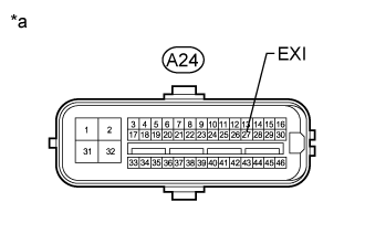
A24-27 (EXI) - Body ground
| Ignition switch ON
| 11 to 14 V
|
Text in Illustration*a
| Front view of wire harness connector
(to Skid Control ECU [Master Cylinder Solenoid])
|
Clear the DTCs (Click here).
Turn the ignition switch off.
Check for DTCs (Click here).
ResultResult
| Proceed to
|
DTC is not output
| A
|
DTC is output (for LHD)
| B
|
DTC is output (for RHD)
| C
|
| 3.CHECK HARNESS AND CONNECTOR (SKID CONTROL ECU - 4 WHEEL DRIVE CONTROL ECU/TRANSFER SHIFT ACTUATOR) |
Disconnect the A24 skid control ECU (master cylinder solenoid) connector.
Disconnect the A27 4 wheel drive control ECU connector.
Disconnect the C37 transfer shift actuator assembly connector.
Measure the resistance according to the value(s) in the table below.
- Standard Resistance:
Tester Connection
| Condition
| Specified Condition
|
A24-27 (EXI) - A27-1 (P1)
| Always
| Below 1 Ω
|
A24-27 (EXI) - C37-3 (CDL)
| Always
| Below 1 Ω
|
A24-27 (EXI) - Body ground
| Always
| 10 kΩ or higher
|
C37-7 (GND1) - Body ground
| Always
| Below 1 Ω
|
| | REPAIR OR REPLACE HARNESS OR CONNECTOR |
|
|
| OK |
|
|
|
| GO TO TRANSFER SYSTEM (PROBLEM SYMPTOMS TABLE) (Click here) |
|