Navigation System Reverse Signal Circuit
DESCRIPTION
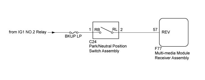
WIRING DIAGRAM
INSPECTION PROCEDURE
CHECK VEHICLE SIGNAL (OPERATION CHECK)
CHECK MULTI-MEDIA MODULE RECEIVER ASSEMBLY
CHECK HARNESS AND CONNECTOR (MULTI-MEDIA MODULE RECEIVER ASSEMBLY - PARK/NEUTRAL POSITION SWITCH ASSEMBLY)
CHECK HARNESS AND CONNECTOR (PARK/NEUTRAL POSITION SWITCH ASSEMBLY - BATTERY)
NAVIGATION SYSTEM - Reverse Signal Circuit |
DESCRIPTION
The multi-media module receiver assembly receives a reverse signal from the park/neutral position switch assembly.
WIRING DIAGRAM
INSPECTION PROCEDURE
- NOTICE:
- Depending on the parts that are replaced during vehicle inspection or maintenance, performing initialization, registration or calibration may be needed. Refer to Precaution for Navigation System (Click here).
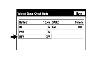
| 1.CHECK VEHICLE SIGNAL (OPERATION CHECK) |
Enter the "Vehicle Signal Check Mode" screen. [Refer to check Vehicle Signal in Operation Check (Click here)].
Check that the display changes between ON and OFF according to the shift lever position.
- OK:
Shift Lever Position
| Display
|
R
| ON
|
Except R
| OFF
|
- HINT:
- This display is updated once per second. As a result, it is normal for the display to lag behind the actual shift lever position.
| OK |
|
|
|
| PROCEED TO NEXT SUSPECTED AREA SHOWN IN PROBLEM SYMPTOMS TABLE (Click here) |
|
| 2.CHECK MULTI-MEDIA MODULE RECEIVER ASSEMBLY |
Disconnect the multi-media module receiver assembly connector.
Measure the voltage according to the value(s) in the table below.
- Standard Voltage:
Tester Connection
| Switch Condition
| Specified Condition
|
F77-57 (REV) - Body ground
| Engine switch on (IG), shift lever in R
| 7.5 to 14 V
|
F77-57 (REV) - Body ground
| Engine switch on (IG), shift lever not in R
| Below 1 V
|
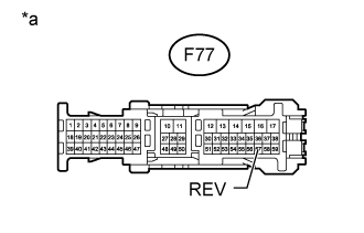
Text in Illustration*a
| Front view of wire harness connector
(to Multi-media Module Receiver Assembly)
|
| OK |
|
|
|
| REPLACE MULTI-MEDIA MODULE RECEIVER ASSEMBLY (Click here) |
|
| 3.CHECK HARNESS AND CONNECTOR (MULTI-MEDIA MODULE RECEIVER ASSEMBLY - PARK/NEUTRAL POSITION SWITCH ASSEMBLY) |
Disconnect the F77 multi-media module receiver assembly connector.
Disconnect the C24 park/neutral position switch assembly connector.
Measure the resistance according to the value(s) in the table below.
- Standard Resistance:
Tester Connection
| Condition
| Specified Condition
|
F77-57 (REV) - C24-2 (RL)
| Always
| Below 1 Ω
|
F77-57 (REV) - Body ground
| Always
| 10 kΩ or higher
|
| | REPAIR OR REPLACE HARNESS OR CONNECTOR |
|
|
| 4.CHECK HARNESS AND CONNECTOR (PARK/NEUTRAL POSITION SWITCH ASSEMBLY - BATTERY) |
Disconnect the park/neutral position switch assembly connector.
Measure the voltage according to the value(s) in the table below.
- Standard Voltage:
Tester Connection
| Switch Condition
| Specified Condition
|
C24-1 (RB) - Body ground
| Engine switch on (IG)
| 11 to 14 V
|
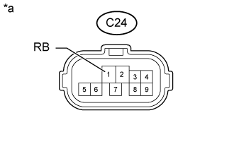
Text in Illustration*a
| Front view of wire harness connector
(to Park/neutral Position Switch Assembly)
|
ResultResult
| Proceed to
|
OK (for A750F)
| A
|
OK (for AB60F)
| B
|
OK (for AE80F)
| C
|
NG
| D
|
| | REPLACE PARK/NEUTRAL POSITION SWITCH ASSEMBLY (Click here) |
|
|
| | REPLACE PARK/NEUTRAL POSITION SWITCH ASSEMBLY (Click here) |
|
|
| | REPAIR OR REPLACE HARNESS OR CONNECTOR |
|
|
| A |
|
|
|
| REPLACE PARK/NEUTRAL POSITION SWITCH ASSEMBLY (Click here) |
|