Navigation System Display Signal Circuit Between Multi-Display And Radio Receiver
DESCRIPTION
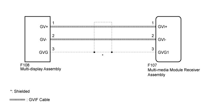
WIRING DIAGRAM
INSPECTION PROCEDURE
CHECK GVIF CABLE CONNECTOR
CHECK MULTI-DISPLAY ASSEMBLY
NAVIGATION SYSTEM - Display Signal Circuit between Multi-display and Radio Receiver |
DESCRIPTION
The display image signal from the multi-media module receiver assembly is sent to the multi-display assembly using a GVIF cable.
WIRING DIAGRAM
INSPECTION PROCEDURE
| 1.CHECK GVIF CABLE CONNECTOR |
Check if the GVIF cable connector between the multi-media module receiver assembly and the multi-display assembly has any connection problems.
Check that the screen display is normal.
- OK:
- Screen display is normal.
| 2.CHECK MULTI-DISPLAY ASSEMBLY |
Replace the multi-display assembly with a new or normally functioning one (Click here).
Check that the screen display is normal.
- OK:
- Screen display is normal.
| | PROCEED TO NEXT SUSPECTED AREA SHOWN IN PROBLEM SYMPTOMS TABLE (Click here) |
|
|
| OK |
|
|
|
| END (MULTI-DISPLAY ASSEMBLY IS DEFECTIVE) |
|