Multi-Terrain Monitor System Chk Message(S) Are Displayed On The Signal Check Screen.
DESCRIPTION
WIRING DIAGRAM
INSPECTION PROCEDURE
CHECK DISPLAY CHECK MODE
INSPECT MAIN SWITCH ASSEMBLY (MULTI-TERRAIN MONITOR MAIN SWITCH)
CHECK HARNESS AND CONNECTOR (MAIN SWITCH ASSEMBLY [MULTI-TERRAIN MONITOR MAIN SWITCH] - PARKING ASSIST ECU AND BATTERY)
MULTI-TERRAIN MONITOR SYSTEM - "CHK" message(s) are displayed on the SIGNAL CHECK screen. |
DESCRIPTION
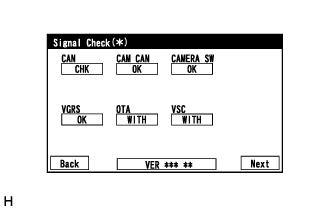
On the SIGNAL CHECK screen, it is possible to check if the signals sent to the parking assist ECU are normal (Click here).- HINT:
- On the SIGNAL CHECK screen, "OK" (blue) is displayed for items with a normal inspection result or input state.
- On the SIGNAL CHECK screen, "CHK" (red) is displayed for items with an abnormal inspection result or input state.
- Displayed items may differ depending on vehicle specifications.
Item
| Signal Input Method
| Detail
| DTC Output when Abnormal Result is Displayed
| Signal Receiver
|
CAN
| CAN communication
| CAN communication signal
| DTC is not output
| Related ECUs
|
CAM CAN
| CAN communication
| CAN communication signal
| DTC is output
| - Front television camera assembly
- Rear television camera assembly
- Side television camera assembly LH
- Side television camera assembly RH
|
CAMERA SW
| Vehicle wire harness
| Main switch assembly (multi-terrain monitor main switch) signal
| DTC is not output
| Main switch assembly (multi-terrain monitor main switch)
|
VGRS
| CAN communication
| VGRS information signal
| DTC is output
| Steering control ECU
|
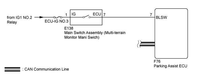
WIRING DIAGRAM
INSPECTION PROCEDURE
- NOTICE:
- When "!" mark is displayed on the multi-display assembly after the battery cable is disconnected, correct the steering angle neutral point (Click here).
- Depending on the parts that are replaced or operations that are performed during vehicle inspection or maintenance, calibration of other systems as well as the multi-terrain monitor system may be needed (Click here).
- Inspect the fuses for circuits related to this system before performing the following inspection procedure.
| 1.CHECK DISPLAY CHECK MODE |
Check which items display on the SIGNAL CHECK screen.
ResultResult
| Proceed to
|
"CAMERA SW" displays "CHK" (red)
| A
|
"CAN" or "VGRS" displays "CHK" (red) (for LHD with Central Gateway ECU)
| B
|
"CAN" or "VGRS" displays "CHK" (red) (for RHD with Central Gateway ECU)
| C
|
"CAM CAN" displays "CHK" (red)
| D
|
| 2.INSPECT MAIN SWITCH ASSEMBLY (MULTI-TERRAIN MONITOR MAIN SWITCH) |
Remove the main switch assembly (multi-terrain monitor main switch) (Click here).
Inspect the main switch assembly (multi-terrain monitor main switch) (Click here).
| | REPLACE MAIN SWITCH ASSEMBLY (MULTI-TERRAIN MONITOR MAIN SWITCH) (Click here) |
|
|
| 3.CHECK HARNESS AND CONNECTOR (MAIN SWITCH ASSEMBLY [MULTI-TERRAIN MONITOR MAIN SWITCH] - PARKING ASSIST ECU AND BATTERY) |
Disconnect the E138 main switch assembly (multi-terrain monitor main switch) connector.
Disconnect the F76 parking assist ECU connector.
Measure the resistance according to the value(s) in the table below.
- Standard Resistance:
Tester Connection
| Condition
| Specified Condition
|
E138-7 (ECU) - F76-7 (BLSW)
| Always
| Below 1 Ω
|
E138-7 (ECU) or F76-7 (BLSW) - Body ground
| Always
| 10 kΩ or higher
|
Measure the voltage according to the value(s) in the table below.
- Standard Voltage:
Tester Connection
| Switch Condition
| Specified Condition
|
E138-1 (IG) - Body ground
| Engine switch on (IG)
| 11 to 14 V
|
E138-1 (IG) - Body ground
| Engine switch off
| Below 1 V
|
| | REPAIR OR REPLACE HARNESS OR CONNECTOR |
|
|