INSTALL LOWER INSTRUMENT PANEL SUB-ASSEMBLY (w/o Driver Side Knee Airbag)
INSTALL DRIVER SIDE KNEE AIRBAG ASSEMBLY (w/ Driver Side Knee Airbag)
INSTALL NO. 1 INSTRUMENT PANEL UNDER COVER SUB-ASSEMBLY (w/ Cover)
Main Body Ecu (For Lhd) -- Installation |
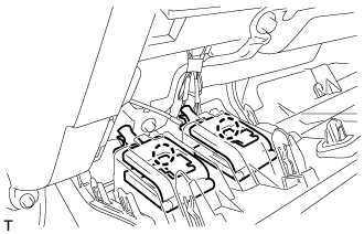
| 1. INSTALL MAIN BODY ECU (MULTIPLEX NETWORK BODY ECU) |
- NOTICE:
- If the main body ECU (multiplex network body ECU) is replaced, refer to service bulletin.
- Make sure that the connecting surfaces are free of foreign matter.
- Do not touch the main body ECU (multiplex network body ECU) connector.
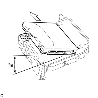
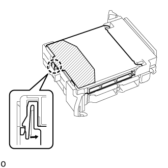
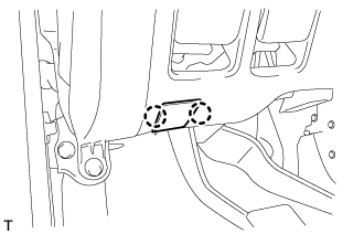
Insert the main body ECU (multiplex network body ECU) up to the position where it contacts the housing sidewall as shown in the illustration.
Text in Illustration *a 20° 
Insert 
Housing Sidewall - HINT:
- Make sure to keep the angle 20° or more as shown in the illustration.
 |
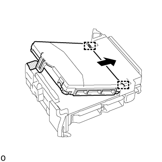
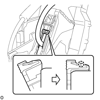
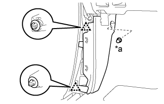
Slide the main body ECU (multiplex network body ECU) along the housing sidewall so that it attaches to the 2 guides.
Text in Illustration 
Slide Housing Sidewall
 |
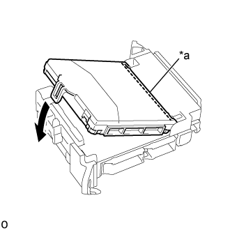
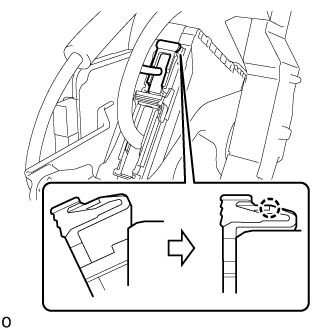
While keeping the main body ECU (multiplex network body ECU) in contact with side A of the cowl side junction block LH (axis of rotation), rotate it downward as shown in the illustration.
Text in Illustration *a Side A Contact Portion
 |
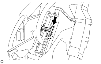
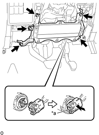
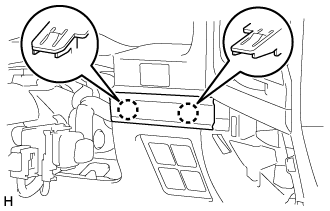
Press the push area until the claw engages to install the main body ECU (multiplex network body ECU).
Text in Illustration Push Area - NOTICE:
- Make sure to press only the push area.
- Confirm the engagement of the main body ECU (multiplex network body ECU) and cowl side junction block LH by listening for the "click" sound of the lock engaging.
- HINT:
- If a "click" sound cannot be heard, visually check the engagement of the lock. The engagement can also be confirmed if the main body ECU (multiplex network body ECU) and cowl side junction block LH are flush.
 |
| 2. INSTALL JUNCTION BLOCK BRACKET |
Attach the guide to install the junction block bracket.
Install the bolt.
- Torque:
- 7.6 N*m{77 kgf*cm, 67 in.*lbf}
| 3. INSTALL STEERING CONTROL ECU (w/ VGRS) |
Attach the 2 claws and install the steering control ECU to the junction block with the 2 bolts.
- Torque:
- 8.0 N*m{82 kgf*cm, 71 in.*lbf}
| 4. INSTALL COWL SIDE JUNCTION BLOCK LH |
Connect the connector with lock lever.
Connect the connector.
Push the lock lever to attach the claw.
 |
Slide the connector lock to attach the claw.
 |
Connect the connector with lock lever.
Connect the connector.
Push the lock lever to attach the claw.
 |
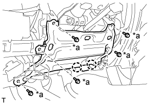
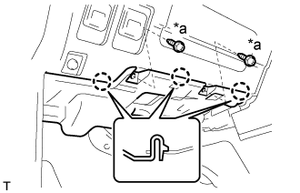
Install the cowl side junction block LH with the 2 nuts and bolt.
- Torque:
- for Nut:
- 7.6 N*m{77 kgf*cm, 67 in.*lbf}
- for Bolt:
- 7.6 N*m{77 kgf*cm, 67 in.*lbf}
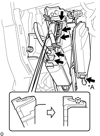
Connect the connector with lock lever.
Text in Illustration *A w/ VGRS Connector 
Connector with Lock Lever - HINT:
- Use the same procedure to connect the connector with lock lever on the other side.
Connect the connector.
Push the lock lever to attach the claw.
 |
Connect each connector.
| 5. INSTALL LOWER INSTRUMENT PANEL SUB-ASSEMBLY (w/o Driver Side Knee Airbag) |
 |
Attach the 2 claws and connect the DLC3.
Install the lower instrument panel sub-assembly with the 5 bolts.
Text in Illustration *a Bolt <B>
| 6. INSTALL DRIVER SIDE KNEE AIRBAG ASSEMBLY (w/ Driver Side Knee Airbag) |
Check that the ignition switch is off.
Check that the cable is disconnected from the negative (-) battery terminal.
- CAUTION:
- Wait at least 90 seconds after disconnecting the cable from the negative (-) battery terminal to disable the SRS system.
Connect the airbag connector and lock the connector lock.
Text in Illustration *a Connector Lock - NOTICE:
- When handling the airbag connector, take care not to damage the airbag wire harness.
 |
Install the driver side knee airbag assembly with the 5 bolts.
- Torque:
- 12 N*m{122 kgf*cm, 9 ft.*lbf}
| 7. INSTALL LOWER NO. 1 INSTRUMENT PANEL FINISH PANEL |
Connect the connectors.
Attach the 2 claws to connect the 2 control cables.
 |
for Automatic Air Conditioning System:
Attach the 2 claws to install the room temperature sensor.

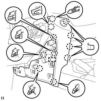
w/ Driver Side Knee Airbag:
Attach the 16 claws to install the lower No. 1 instrument panel finish panel.
w/o Driver Side Knee Airbag:
Attach the 9 claws to install the lower No. 1 instrument panel finish panel.
Install the 2 bolts <B>.
Text in Illustration *a Bolt <B>
 |
Attach the 2 claws to close the hole cover.
 |
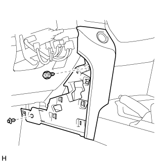
| 8. INSTALL COWL SIDE TRIM BOARD LH |
 |
Attach the 2 clips to install the cowl side trim board LH.
Install the cap nut.
Text in Illustration *a Cap Nut
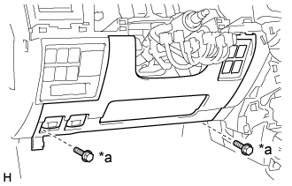
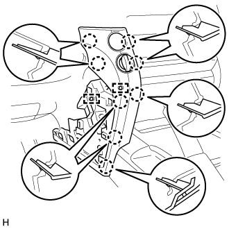
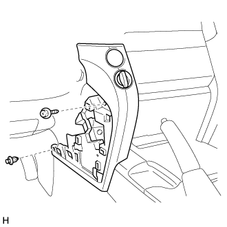
| 9. INSTALL NO. 1 INSTRUMENT PANEL UNDER COVER SUB-ASSEMBLY (w/ Cover) |
 |
Connect the connector.
Attach the 3 claws to install the No. 1 instrument panel under cover sub-assembly.
Install the 2 screws <A>.
Text in Illustration *a Screw <A>
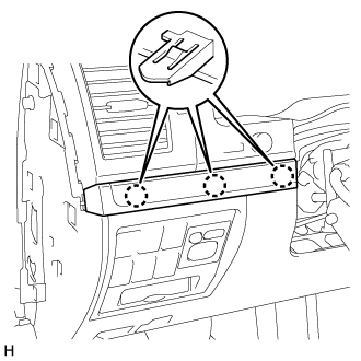
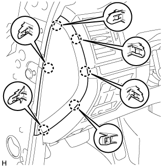
| 10. INSTALL NO. 2 INSTRUMENT CLUSTER FINISH PANEL GARNISH |
 |
Attach the 2 claws to install the No. 2 instrument cluster finish panel garnish.
| 11. INSTALL NO. 1 INSTRUMENT CLUSTER FINISH PANEL GARNISH |
 |
Attach the 3 claws to install the No. 1 instrument cluster finish panel garnish.
| 12. INSTALL LOWER INSTRUMENT PANEL PAD SUB-ASSEMBLY LH |
for Type A:
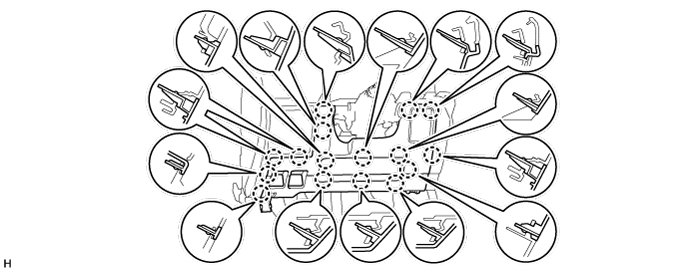
Connect the connectors and clamps.
Attach the 11 claws and guide to install the lower instrument panel pad sub-assembly LH.
Install the screw and clip.
for Type B:
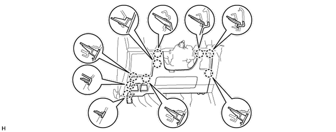
Connect the connectors and clamps.
Attach the 8 claws and 2 guides to install the lower instrument panel pad sub-assembly LH.
Install the screw and clip.
| 13. INSTALL NO. 2 INSTRUMENT PANEL FINISH PANEL CUSHION |
for Type A:
Attach the 4 claws and 3 clips to install the No. 2 instrument panel finish panel cushion.
for Type B:
Attach the 7 claws to install the No. 2 instrument panel finish panel cushion.
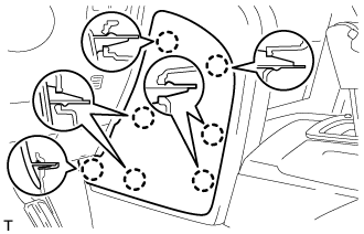
| 14. INSTALL FRONT DOOR SCUFF PLATE LH |
 |
Attach the 7 claws and 4 clips to install the front door scuff plate LH.
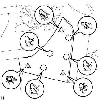
| 15. INSTALL INSTRUMENT SIDE PANEL LH |
 |
Attach the 6 claws to install the instrument side panel LH.
| 16. CONNECT CABLE TO NEGATIVE BATTERY TERMINAL |
- NOTICE:
- When disconnecting the cable, some systems need to be initialized after the cable is reconnected (Click here).