DESCRIPTION
WIRING DIAGRAM
INSPECTION PROCEDURE
CHECK VEHICLE TYPE
CHECK CAN COMMUNICATION SYSTEM
CHECK OPERATION
INSPECT TEMPERATURE CONTROL SWITCH ASSEMBLY LH
CHECK HARNESS AND CONNECTOR (TEMPERATURE CONTROL SWITCH ASSEMBLY LH - MULTI-DISPLAY ASSEMBLY)
INSPECT TEMPERATURE CONTROL SWITCH ASSEMBLY RH
CHECK HARNESS AND CONNECTOR (TEMPERATURE CONTROL SWITCH ASSEMBLY RH - MULTI-DISPLAY ASSEMBLY)
CHECK MULTI-DISPLAY ASSEMBLY
CHECK LIN COMMUNICATION SYSTEM
CHECK OPERATION
INSPECT TEMPERATURE CONTROL SWITCH ASSEMBLY LH
CHECK HARNESS AND CONNECTOR (TEMPERATURE CONTROL SWITCH ASSEMBLY LH - AIR CONDITIONING CONTROL ASSEMBLY)
INSPECT TEMPERATURE CONTROL SWITCH ASSEMBLY RH
CHECK HARNESS AND CONNECTOR (TEMPERATURE CONTROL SWITCH ASSEMBLY RH - AIR CONDITIONING CONTROL ASSEMBLY)
CHECK AIR CONDITIONING CONTROL ASSEMBLY
AIR CONDITIONING SYSTEM (for Automatic Air Conditioning System) - Heater Control Switch Circuit |
DESCRIPTION
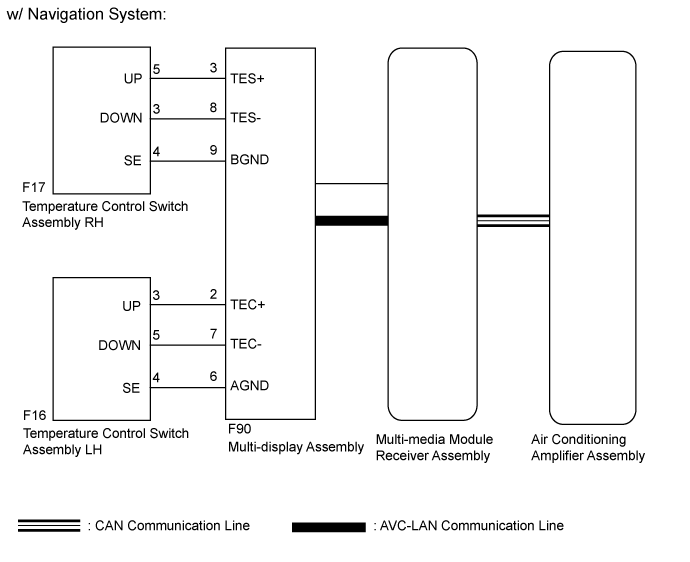
The temperature control switch assembly LH and RH sends the temperature up and down signal to the air conditioning amplifier assembly through the multi-display assembly*1 or the air conditioning control assembly*2.- *1: w/ Navigation System
- *2: w/o Navigation System
WIRING DIAGRAM
INSPECTION PROCEDURE
Check if the vehicle is equipped with the navigation system.
ResultResult
| Proceed to
|
w/ Navigation System
| A
|
w/o Navigation System
| B
|
| 2.CHECK CAN COMMUNICATION SYSTEM |
Check the CAN communication system.
- OK:
- CAN communication system has no problem.
ResultResult
| Proceed to
|
OK
| A
|
NG (for LHD)
| B
|
NG (for RHD)
| C
|
Check that the temperature control switches operate.
ResultResult
| Proceed to
|
Temperature control switch LH does not operate
| A
|
Temperature control switch RH does not operate
| B
|
Temperature control switch LH and RH do not operate
| C
|
| 4.INSPECT TEMPERATURE CONTROL SWITCH ASSEMBLY LH |
Remove the temperature control switch assembly LH (Click here).
Measure the resistance according to the value(s) in the table below.
- Standard Resistance:
Tester Connection
| Switch Condition
| Specified Condition
|
3 (UP) - 4 (SE)
| UP switch pressed
| Below 1 Ω
|
UP switch not pressed
| 10 kΩ or higher
|
5 (DOWN) - 4 (SE)
| DOWN switch pressed
| Below 1 Ω
|
DOWN switch not pressed
| 10 kΩ or higher
|
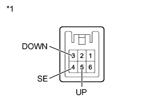
Text in Illustration*1
| Component without harness connected
(Temperature Control Switch Assembly LH)
|
| | REPLACE TEMPERATURE CONTROL SWITCH ASSEMBLY LH (Click here) |
|
|
| 5.CHECK HARNESS AND CONNECTOR (TEMPERATURE CONTROL SWITCH ASSEMBLY LH - MULTI-DISPLAY ASSEMBLY) |
Disconnect the F16 temperature control switch assembly LH connector.
Disconnect the F90 multi-display assembly connector.
Measure the resistance according to the value(s) in the table below.
- Standard Resistance:
Tester Connection
| Condition
| Specified Condition
|
F16-3 (UP) - F90-2 (TEC+)
| Always
| Below 1 Ω
|
F16-5 (DOWN) - F90-7 (TEC-)
| Always
| Below 1 Ω
|
F16-4 (SE) - F90-6 (AGND)
| Always
| Below 1 Ω
|
F16-3 (UP) - Body ground
| Always
| 10 kΩ or higher
|
F16-5 (DOWN) - Body ground
| Always
| 10 kΩ or higher
|
F16-4 (SE) - Body ground
| Always
| 10 kΩ or higher
|
| | REPAIR OR REPLACE HARNESS OR CONNECTOR |
|
|
| 6.INSPECT TEMPERATURE CONTROL SWITCH ASSEMBLY RH |
Remove the temperature control switch assembly RH (Click here).
Measure the resistance according to the value(s) in the table below.
- Standard Resistance:
Tester Connection
| Switch Condition
| Specified Condition
|
5 (UP) - 4 (SE)
| UP switch pressed
| Below 1 Ω
|
UP switch not pressed
| 10 kΩ or higher
|
3 (DOWN) - 4 (SE)
| DOWN switch pressed
| Below 1 Ω
|
DOWN switch not pressed
| 10 kΩ or higher
|
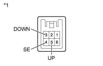
Text in Illustration*1
| Component without harness connected
(Temperature Control Switch Assembly RH)
|
| | REPLACE TEMPERATURE CONTROL SWITCH ASSEMBLY RH (Click here) |
|
|
| 7.CHECK HARNESS AND CONNECTOR (TEMPERATURE CONTROL SWITCH ASSEMBLY RH - MULTI-DISPLAY ASSEMBLY) |
Disconnect the F17 temperature control switch assembly RH connector.
Disconnect the F90 multi-display assembly connector.
Measure the resistance according to the value(s) in the table below.
- Standard Resistance:
Tester Connection
| Condition
| Specified Condition
|
F17-5 (UP) - F90-3 (TES+)
| Always
| Below 1 Ω
|
F17-3 (DOWN) - F90-8 (TES-)
| Always
| Below 1 Ω
|
F17-4 (SE) - F90-9 (BGND)
| Always
| Below 1 Ω
|
F17-5 (UP) - Body ground
| Always
| 10 kΩ or higher
|
F17-3 (DOWN) - Body ground
| Always
| 10 kΩ or higher
|
F17-4 (SE) - Body ground
| Always
| 10 kΩ or higher
|
| | REPAIR OR REPLACE HARNESS OR CONNECTOR |
|
|
| 8.CHECK MULTI-DISPLAY ASSEMBLY |
Replace the multi-display assembly with a new or normally functioning one (Click here).
Check that the temperature control with temperature control switch LH and RH.
- OK:
- Temperature control with temperature control switch LH and RH.
| | PROCEED TO NEXT SUSPECTED AREA SHOWN IN PROBLEM SYMPTOMS TABLE (Click here) |
|
|
| OK |
|
|
|
| END (MULTI-DISPLAY ASSEMBLY IS DEFECTIVE) |
|
| 9.CHECK LIN COMMUNICATION SYSTEM |
Check the LIN communication system.
- OK:
- LIN communication system has no problem.
Check that the temperature control switches operate.
ResultResult
| Proceed to
|
Temperature control switch LH does not operate
| A
|
Temperature control switch RH does not operate
| B
|
Temperature control switch LH and RH do not operate
| C
|
| 11.INSPECT TEMPERATURE CONTROL SWITCH ASSEMBLY LH |
Remove the temperature control switch assembly LH (Click here).
Measure the resistance according to the value(s) in the table below.
- Standard Resistance:
Tester Connection
| Switch Condition
| Specified Condition
|
3 (UP) - 4 (SE)
| UP switch pressed
| Below 1 Ω
|
UP switch not pressed
| 10 kΩ or higher
|
5 (DOWN) - 4 (SE)
| DOWN switch pressed
| Below 1 Ω
|
DOWN switch not pressed
| 10 kΩ or higher
|
Text in Illustration*1
| Component without harness connected
(Temperature Control Switch Assembly LH)
|
| | REPLACE TEMPERATURE CONTROL SWITCH ASSEMBLY LH (Click here) |
|
|
| 12.CHECK HARNESS AND CONNECTOR (TEMPERATURE CONTROL SWITCH ASSEMBLY LH - AIR CONDITIONING CONTROL ASSEMBLY) |
Disconnect the F16 temperature control switch assembly LH connector.
Disconnect the F10 air conditioning control assembly connector.
Measure the resistance according to the value(s) in the table below.
- Standard Resistance:
Tester Connection
| Condition
| Specified Condition
|
F16-3 (UP) - F10-12 (DTP+)
| Always
| Below 1 Ω
|
F16-5 (DOWN) - F10-11 (DTP-)
| Always
| Below 1 Ω
|
F16-4 (SE) - F10-9 (S5)
| Always
| Below 1 Ω
|
F16-3 (UP) - Body ground
| Always
| 10 kΩ or higher
|
F16-5 (DOWN) - Body ground
| Always
| 10 kΩ or higher
|
F16-4 (SE) - Body ground
| Always
| 10 kΩ or higher
|
| | REPAIR OR REPLACE HARNESS OR CONNECTOR |
|
|
| OK |
|
|
|
| REPLACE AIR CONDITIONING CONTROL ASSEMBLY (Click here) |
|
| 13.INSPECT TEMPERATURE CONTROL SWITCH ASSEMBLY RH |
Remove the temperature control switch assembly RH (Click here).
Measure the resistance according to the value(s) in the table below.
- Standard Resistance:
Tester Connection
| Switch Condition
| Specified Condition
|
5 (UP) - 4 (SE)
| UP switch pressed
| Below 1 Ω
|
UP switch not pressed
| 10 kΩ or higher
|
3 (DOWN) - 4 (SE)
| DOWN switch pressed
| Below 1 Ω
|
DOWN switch not pressed
| 10 kΩ or higher
|
Text in Illustration*1
| Component without harness connected
(Temperature Control Switch Assembly RH)
|
| | REPLACE TEMPERATURE CONTROL SWITCH ASSEMBLY RH (Click here) |
|
|
| 14.CHECK HARNESS AND CONNECTOR (TEMPERATURE CONTROL SWITCH ASSEMBLY RH - AIR CONDITIONING CONTROL ASSEMBLY) |
Disconnect the F17 temperature control switch assembly RH connector.
Disconnect the F10 air conditioning control assembly connector.
Measure the resistance according to the value(s) in the table below.
- Standard Resistance:
Tester Connection
| Condition
| Specified Condition
|
F17-5 (UP) - F10-10 (PTP+)
| Always
| Below 1 Ω
|
F17-3 (DOWN) - F10-3 (PTP-)
| Always
| Below 1 Ω
|
F17-4 (SE) - F10-2 (SG)
| Always
| Below 1 Ω
|
F17-5 (UP) - Body ground
| Always
| 10 kΩ or higher
|
F17-3 (DOWN) - Body ground
| Always
| 10 kΩ or higher
|
F17-4 (SE) - Body ground
| Always
| 10 kΩ or higher
|
| | REPAIR OR REPLACE HARNESS OR CONNECTOR |
|
|
| OK |
|
|
|
| REPLACE AIR CONDITIONING CONTROL ASSEMBLY (Click here) |
|
| 15.CHECK AIR CONDITIONING CONTROL ASSEMBLY |
Replace the air conditioning control assembly with a new or normally functioning one (Click here).
Check that the temperature control with temperature control switch LH and RH.
- OK:
- Temperature control with temperature control switch LH and RH.
| | REPLACE AIR CONDITIONING AMPLIFIER ASSEMBLY (Click here) |
|
|
| OK |
|
|
|
| END (AIR CONDITIONING CONTROL ASSEMBLY IS DEFECTIVE) |
|