Relay -- On-Vehicle Inspection |
| 1. INSPECT MAIN BODY ECU |
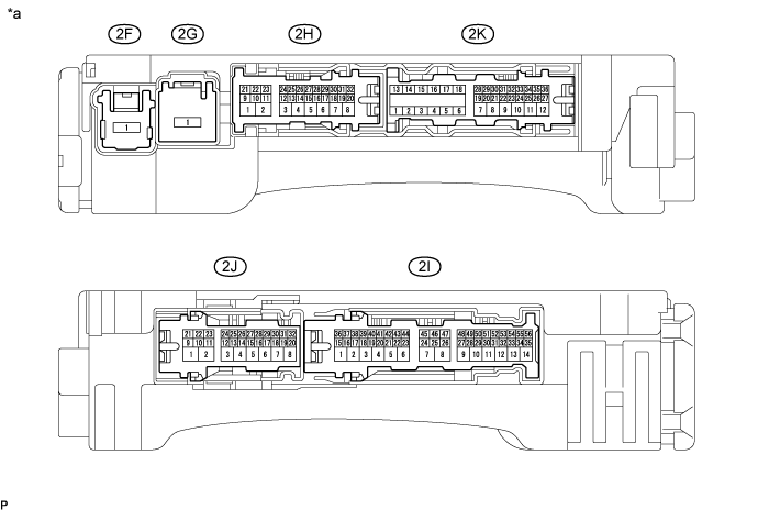
| *a | Component without harness connected (Main Body ECU) | - | - |
- NOTICE:
- The IG1 No. 1 relay, IG1 No. 2 relay and IG1 No. 3 relay are built into the main body ECU.
- Before performing the relay inspections for the relays of the main body ECU, inspect the ECU-IG No. 1, ECU-IG No. 2 and ECU-IG No. 3 fuses.
Inspect the IG1 No. 1 relay.
Measure the resistance according to the value(s) in the table below.
- Standard Resistance:
Tester Connection Condition Specified Condition 2G-1 - 2H-24 Battery voltage is not applied to terminals 2I-18 and 2J-1 10 kΩ or higher Battery voltage is applied to terminals 2I-18 and 2J-1 Below 1 Ω
Inspect the IG1 No. 2 relay.
Measure the resistance according to the value(s) in the table below.
- Standard Resistance:
Tester Connection Condition Specified Condition 2G-1 - 2H-14 Battery voltage is not applied to terminals 2I-18 and 2J-1 10 kΩ or higher Battery voltage is applied to terminals 2I-18 and 2J-1 Below 1 Ω
Inspect the IG1 No. 3 relay.
Measure the resistance according to the value(s) in the table below.
- Standard Resistance:
Tester Connection Condition Specified Condition 2G-1 - 2H-16 Battery voltage is not applied to terminals 2I-18 and 2J-1 10 kΩ or higher Battery voltage is applied to terminals 2I-18 and 2J-1 Below 1 Ω
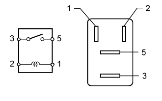
| 2. INSPECT AIR INJECTION VSV RELAY (AI-VSV) |
Measure the resistance according to the value(s) in the table below.
- Standard Resistance:
Tester Connection Condition Specified Condition 3 - 5 Battery voltage is not applied to terminals 1 and 2 10 kΩ or higher Battery voltage is applied to terminals 1 and 2 Below 1 Ω
 |
| 3. INSPECT INTEGRATION RELAY |
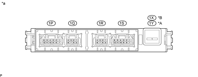
| *A | for LHD | *B | for RHD |
| *a | Component without harness connected (Integration Relay) | - | - |
- NOTICE:
- The IG2 MAIN relay, FUEL PMP relay, EFI MAIN No. 1 relay, A/F relay and AIR PMP HTR relay are built into the integration relay.
- Before performing the relay inspections for the relays of the integration relay, inspect the IG2 MAIN, FUEL PMP, EFI No. 2, EFI MAIN No. 1, A/F HTR and AIR PMP HTR fuses.
Inspect the IG2 MAIN relay.
Measure the resistance according to the value(s) in the table below.
- Standard Resistance:
for LHD: Tester Connection Condition Specified Condition 1Y-1 - 1R-1 Battery voltage is not applied to terminals 1R-2 and 1S-4 10 kΩ or higher Battery voltage is applied to terminals 1R-2 and 1S-4 Below 1 Ω for RHD: Tester Connection Condition Specified Condition 1X-1 - 1R-1 Battery voltage is not applied to terminals 1R-2 and 1S-4 10 kΩ or higher Battery voltage is applied to terminals 1R-2 and 1S-4 Below 1 Ω
Inspect the FUEL PMP relay.
Measure the resistance according to the value(s) in the table below.
- Standard Resistance:
for LHD: Tester Connection Condition Specified Condition 1Y-1 - 1R-6 Battery voltage is not applied to terminals 1R-7 and 1S-12 10 kΩ or higher Battery voltage is applied to terminals 1R-7 and 1S-12 Below 1 Ω for RHD: Tester Connection Condition Specified Condition 1X-1 - 1R-6 Battery voltage is not applied to terminals 1R-7 and 1S-12 10 kΩ or higher Battery voltage is applied to terminals 1R-7 and 1S-12 Below 1 Ω
Inspect the EFI MAIN No. 1 relay.
Measure the resistance according to the value(s) in the table below.
- Standard Resistance:
for LHD: Tester Connection Condition Specified Condition 1Y-1 - 1S-1 Battery voltage is not applied to terminals 1S-8 and 1S-4 10 kΩ or higher Battery voltage is applied to terminals 1S-8 and 1S-4 Below 1 Ω for RHD: Tester Connection Condition Specified Condition 1X-1 - 1S-1 Battery voltage is not applied to terminals 1S-8 and 1S-4 10 kΩ or higher Battery voltage is applied to terminals 1S-8 and 1S-4 Below 1 Ω
Inspect the A/F relay.
Measure the resistance according to the value(s) in the table below.
- Standard Resistance:
for LHD: Tester Connection Condition Specified Condition 1Y-1 - 1S-3 Battery voltage is not applied to terminals 1S-1 and 1S-4 10 kΩ or higher Battery voltage is applied to terminals 1S-1 and 1S-4 Below 1 Ω for RHD: Tester Connection Condition Specified Condition 1X-1 - 1S-3 Battery voltage is not applied to terminals 1S-1 and 1S-4 10 kΩ or higher Battery voltage is applied to terminals 1S-1 and 1S-4 Below 1 Ω
Inspect the AIR PMP HTR relay.
Measure the resistance according to the value(s) in the table below.
- Standard Resistance:
for LHD: Tester Connection Condition Specified Condition 1Y-1 - 1P-9 Battery voltage is not applied to terminals 1Y-1 and 1P-10 10 kΩ or higher for RHD: Tester Connection Condition Specified Condition 1X-1 - 1P-9 Battery voltage is not applied to terminals 1X-1 and 1P-10 10 kΩ or higher
- Standard Voltage:
for LHD: Tester Connection Condition Specified Condition 1P-9 - Battery negative (-) Battery positive (+) → 1Y-1
Battery negative (-) → 1P-1011 to 14 V for RHD: Tester Connection Condition Specified Condition 1P-9 - Battery negative (-) Battery positive (+) → 1X-1
Battery negative (-) → 1P-1011 to 14 V