Steering Column Assembly (For Power Tilt And Power Telescopic Steering Column) On-Vehicle Inspection
Steering. Land Cruiser. Urj200, 202 Grj200 Vdj200
PRECAUTION
DISCONNECT CABLE FROM NEGATIVE BATTERY TERMINAL
REMOVE LOWER STEERING COLUMN COVER
REMOVE DRIVER SIDE KNEE AIRBAG ASSEMBLY
INSPECT TELESCOPIC MOTOR
INSTALL DRIVER SIDE KNEE AIRBAG ASSEMBLY
INSTALL LOWER STEERING COLUMN COVER
CHECK SRS WARNING LIGHT
CONNECT CABLE TO NEGATIVE BATTERY TERMINAL
Steering Column Assembly (For Power Tilt And Power Telescopic Steering Column) -- On-Vehicle Inspection |
- NOTICE:
- After turning the ignition switch off, waiting time may be required before disconnecting the cable from the battery terminal. Therefore, make sure to read the disconnecting the cable from the battery terminal notice before proceeding with work (Click here).
| 2. DISCONNECT CABLE FROM NEGATIVE BATTERY TERMINAL |
Disable the AUTO TILT AWAY function by changing the customize parameter (Click here).
- NOTICE:
- Record the current customize parameter setting (whether the AUTO TILT AWAY function is enabled or disabled) in order to restore the current setting after finishing the operation.
- HINT:
- Performing the above operation causes the AUTO TILT AWAY function to be disabled when the engine switch is turned off.
Turn the engine switch on (IG). Operate the tilt and telescopic switch to fully extend and lower the steering column assembly.
Turn the engine switch off and disconnect the cable from the negative (-) battery terminal.
- CAUTION:
- Wait at least 90 seconds after disconnecting the cable from the negative (-) battery terminal to disable the SRS system.
- NOTICE:
- When disconnecting the cable, some systems need to be initialized after the cable is reconnected (Click here).
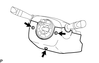
| 3. REMOVE LOWER STEERING COLUMN COVER |
Remove the 3 screws.
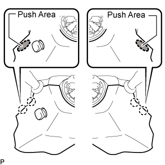
While pressing the push area shown in the illustration to detach the 4 claws, slightly lower steering column cover.
- NOTICE:
- Do not damage the tilt and telescopic switch.
| 4. REMOVE DRIVER SIDE KNEE AIRBAG ASSEMBLY |
(Click here)
| 5. INSPECT TELESCOPIC MOTOR |
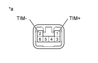
Inspect the tilt motor:
Disconnect the tilt motor connector.
Apply 12 V battery voltage to the tilt motor connector. Then check the steering wheel tilt operation.
OKMeasurement Condition
| Specified Condition
|
12 V battery positive (+) lead → Terminal 1 (TIM+)
12 V battery negative (-) lead → Terminal 2 (TIM-)
| The steering wheel tilts up.
|
12 V battery negative (-) lead → Terminal 1 (TIM+)
12 V battery positive (+) lead → Terminal 2 (TIM-)
| The steering wheel tilts down.
|
If the result is not as specified, replace the steering column assembly.
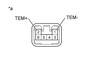
Inspect the telescopic motor:
Disconnect the telescopic motor connector.
Apply 12 V battery voltage to the telescopic motor connector. Then check the steering column telescopic operation.
OKMeasurement Condition
| Specified Condition
|
12 V battery positive (+) lead → Terminal 2 (TEM+)
12 V battery negative (-) lead → Terminal 1 (TEM-)
| The steering column contracts.
|
12 V battery positive (+) lead → Terminal 1 (TEM-)
12 V battery negative (-) lead → Terminal 2 (TEM+)
| The steering column extends.
|
If the result is not as specified, replace the steering column assembly.
| 6. INSTALL DRIVER SIDE KNEE AIRBAG ASSEMBLY |
(Click here)
| 7. INSTALL LOWER STEERING COLUMN COVER |
Attach the 4 claws to install the lower steering column cover.
- NOTICE:
- Do not damage the tilt and telescopic switch.
Install the 3 screws.
- Torque:
- 1.5 N*m{15 kgf*cm, 13 in.*lbf}
| 8. CHECK SRS WARNING LIGHT |
(Click here)
| 9. CONNECT CABLE TO NEGATIVE BATTERY TERMINAL |
- NOTICE:
- When disconnecting the cable, some systems need to be initialized after the cable is reconnected (Click here).