Exhaust Pipe (W/ Dpf) -- Installation |
- CAUTION:
- Wear protective gloves and protective glasses when installing the exhaust pipe.
- The exhaust pipe is extremely hot immediately after the engine has stopped.
- Confirm that the exhaust pipe has cooled down before removing it.
| 1. INSTALL EXHAUST GAS TEMPERATURE SENSOR |
- NOTICE:
- If the sensor is dropped, replace it with a new one.
Using a 14 mm union nut wrench, install the 2 exhaust gas temperature sensors.
- Torque:
- 30 N*m{306 kgf*cm, 22 ft.*lbf}
- NOTICE:
- Use the formula to calculate special torque values for situations where a union nut wrench is combined with a torque wrench (Click here).
- HINT:
- The identification tape on the exhaust gas temperature sensor is pink.
| 2. INSTALL NO. 2 EXHAUST GAS TEMPERATURE SENSOR |
- NOTICE:
- If the sensor is dropped, replace it with a new one.
Using a 14 mm union nut wrench, install the No. 2 exhaust gas temperature sensor.
- Torque:
- 30 N*m{306 kgf*cm, 22 ft.*lbf}
- NOTICE:
- Use the formula to calculate special torque values for situations where a union nut wrench is combined with a torque wrench (Click here).
- HINT:
- The identification tape on the exhaust gas temperature sensor is white.
| 3. INSTALL NO. 3 EXHAUST GAS TEMPERATURE SENSOR |
- NOTICE:
- If the sensor is dropped, replace it with a new one.
Using a 14 mm union nut wrench, install the No. 3 exhaust gas temperature sensor.
- Torque:
- 30 N*m{306 kgf*cm, 22 ft.*lbf}
- NOTICE:
- Use the formula to calculate special torque values for situations where a union nut wrench is combined with a torque wrench (Click here).
- HINT:
- The identification tape on the exhaust gas temperature sensor is gray.
| 4. INSTALL MONOLITHIC CONVERTER ASSEMBLY LH |
Install a new gasket to the turbocharger.
- HINT:
- Make sure that the claw of the gasket faces downward.
Install the monolithic converter LH with 3 new nuts.
- Torque:
- 47 N*m{479 kgf*cm, 35 ft.*lbf}
 |
Temporarily install the No. 2 manifold stay with the 3 bolts.
Tighten the 2 bolts labeled A in the illustration first, and then tighten the bolt labeled B in the illustration.
- Torque:
- 43 N*m{438 kgf*cm, 32 ft.*lbf}
Attach the 4 clamps and connect the 2 exhaust gas temperature sensor connectors.
Text in Illustration *1 Tape - HINT:
- Make sure that the tape is in the position shown in the illustration.
 |
| 5. INSTALL FRONT PROPELLER SHAFT ASSEMBLY |
| 6. INSTALL MONOLITHIC CONVERTER ASSEMBLY RH |
Install a new gasket to the turbocharger.
- HINT:
- Make sure that the claw of the gasket faces the transmission.
Install the monolithic converter RH with 3 new nuts.
- Torque:
- 47 N*m{479 kgf*cm, 35 ft.*lbf}
 |
Temporarily install the manifold stay with the 3 bolts.
Tighten the 2 bolts labeled A in the illustration first, and then tighten the bolt labeled B in the illustration.
- Torque:
- 43 N*m{438 kgf*cm, 32 ft.*lbf}
Attach the 4 clamps and connect the 2 exhaust gas temperature sensor connectors.
| 7. INSTALL NO. 4 EXHAUST GAS TEMPERATURE SENSOR |
- NOTICE:
- If the sensor is dropped, replace it with a new one.
Using a 14 mm union nut wrench, install the 2 No. 4 exhaust gas temperature sensors.
- Torque:
- 30 N*m{306 kgf*cm, 22 ft.*lbf}
- NOTICE:
- Use the formula to calculate special torque values for situations where a union nut wrench is combined with a torque wrench (Click here).
- HINT:
- The identification tape on the exhaust gas temperature sensor is gold.
| 8. INSTALL FRONT NO. 2 EXHAUST PIPE ASSEMBLY |
Install a new gasket and the front No. 2 exhaust pipe to the monolithic converter LH with 3 new nuts.
- Torque:
- 48 N*m{489 kgf*cm, 35 ft.*lbf}
Attach the clamp and connect the exhaust gas temperature sensor connector.
Text in Illustration *1 Tape *2 Stopper *3 Clip *a 2 to 7 mm (0.0787 to 0.276 in.) 
Paint Mark - HINT:
- Make sure that the tape is in the position shown in the illustration.
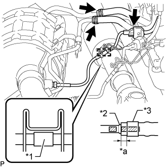 |
Install 2 new clips to the 2 air hoses.
Connect the 2 air hoses to the front No. 2 exhaust pipe.
- NOTICE:
- Align the paint marks of the front No. 2 exhaust pipe and air hose and push on the air hose until it contacts the stopper.
- Make sure the clip is 4 to 10 mm (0.157 to 0.394 in.) from the end of the air hose when installing the clip.
- Make sure that there is no slack in the air hose, and that it is not twisted or bent.
- Take care not to damage the inner or outer surface of the air hose when installing it. If the air hose is damaged, replace it with a new one.
| 9. INSTALL NO. 5 EXHAUST PIPE ASSEMBLY |
Install a new gasket and the No. 5 exhaust pipe to the front No. 2 exhaust pipe with 2 new nuts.
- Torque:
- 48 N*m{489 kgf*cm, 35 ft.*lbf}
| 10. INSTALL FRONT EXHAUST PIPE ASSEMBLY |
Install a new gasket and the front exhaust pipe to the monolithic converter RH with 3 new nuts.
- Torque:
- 48 N*m{489 kgf*cm, 35 ft.*lbf}
Attach the clamp and connect the exhaust gas temperature sensor connector.
Text in Illustration *1 Tape *2 Stopper *3 Clip *a 2 to 7 mm (0.0787 to 0.276 in.) Paint Mark - HINT:
- Make sure that the tape is in the position shown in the illustration.
 |
Install 2 new clips to the 2 air hoses.
Connect the 2 air hoses to the front exhaust pipe assembly, and slide the 2 clamps to secure the hose.
- NOTICE:
- Align the paint marks of the front exhaust pipe and air hose and push on the air hose until it contacts the stopper.
- Make sure the clip is 4 to 10 mm (0.157 to 0.394 in.) from the end of the air hose when installing the clip.
- Make sure that there is no slack in the air hose, and that it is not twisted or bent.
- Take care not to damage the inner or outer surface of the air hose when installing it. If the air hose is damaged, replace it with a new one.
| 11. INSTALL OIL PAN PROTECTOR ASSEMBLY RH (for 2-piece Type) |
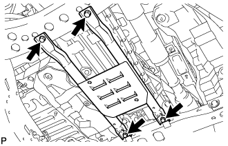
Install the oil pan protector assembly RH with the 4 bolts.
- Torque:
- 50 N*m{510 kgf*cm, 37 ft.*lbf}
 |
| 12. INSTALL OIL PAN PROTECTOR ASSEMBLY LH (for 2-piece Type) |
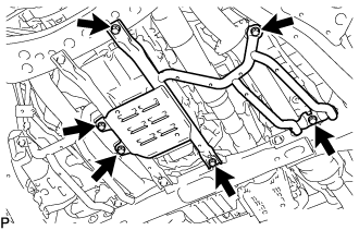
Install the oil pan protector assembly LH with the 6 bolts.
- Torque:
- 50 N*m{510 kgf*cm, 37 ft.*lbf}
 |
| 13. INSTALL OIL PAN PROTECTOR ASSEMBLY (for 1-piece Type) |
 |
Install the oil pan protector assembly with the 4 bolts.
- Torque:
- 50 N*m{510 kgf*cm, 37 ft.*lbf}
| 14. INSTALL CENTER EXHAUST PIPE ASSEMBLY |
Check the free length.
Using a vernier caliper, measure the free length of the compression spring.
- Free length:
- 43 mm (1.69 in.)
 |
Connect the center exhaust pipe to the 3 exhaust pipe supports.
Install 2 new gaskets to the No. 5 exhaust pipe and front exhaust pipe.
Install the center exhaust pipe with the 4 bolts and 2 compression springs.
- Torque:
- for center exhaust pipe and front exhaust pipe:
- 43 N*m{438 kgf*cm, 32 ft.*lbf}
- for center exhaust pipe and No. 5 exhaust pipe:
- 48 N*m{489 kgf*cm, 35 ft.*lbf}
| 15. INSTALL TAILPIPE ASSEMBLY |
Connect the tailpipe to the 2 exhaust pipe supports.
Text in Illustration *1 Gasket *a Top *b LH Side 
Front
 |
Install a new gasket to the center exhaust pipe.
Connect the tailpipe to the center exhaust pipe with a new clamp.
- HINT:
- Install the clamp within the angle range shown in the illustration.
Tighten the bolt.
- Torque:
- 32 N*m{326 kgf*cm, 24 ft.*lbf}
| 16. INSTALL AIR FUEL RATIO SENSOR |
| 17. INSPECT FOR EXHAUST GAS LEAK |
| 18. INSTALL NO. 2 ENGINE UNDER COVER |
Install the No. 2 engine under cover with the 6 bolts.
- Torque:
- 29 N*m{296 kgf*cm, 21 ft.*lbf}
| 19. INSTALL FRONT FENDER APRON SEAL REAR LH |
Install the front fender apron seal rear LH with the 4 clips.
| 20. INSTALL FRONT FENDER APRON SEAL REAR RH |
Install the front fender apron seal rear RH with the 4 clips.
| 21. PERFORM CATALYST RECORD OF DPF THERMAL DETERIORATION CLEAR FUNCTION |