Rear Seat Entertainment Ecu Removal
PRECAUTION
DISCONNECT CABLE FROM NEGATIVE BATTERY TERMINAL
REMOVE FRONT SEAT ASSEMBLY RH
REMOVE INSTRUMENT SIDE PANEL RH
REMOVE FRONT DOOR SCUFF PLATE RH
REMOVE COWL SIDE TRIM BOARD RH
REMOVE FRONT FLOOR CARPET ASSEMBLY
REMOVE MULTI-DISPLAY CONTROLLER SUB-ASSEMBLY
REMOVE NO. 2 MULTI-DISPLAY CONTROLLER BRACKET
REMOVE NO. 3 MULTI-DISPLAY CONTROLLER BRACKET
REMOVE FRONT CONSOLE BOX
REMOVE NO. 1 NAVIGATION WIRE
Rear Seat Entertainment Ecu -- Removal |
- NOTICE:
- After turning the ignition switch off, waiting time may be required before disconnecting the cable from the battery terminal. Therefore, make sure to read the disconnecting the cable from the battery terminal notice before proceeding with work (Click here).
| 2. DISCONNECT CABLE FROM NEGATIVE BATTERY TERMINAL |
- CAUTION:
- Wait at least 90 seconds after disconnecting the cable from the negative (-) battery terminal to disable the SRS system.
- NOTICE:
- When disconnecting the cable, some systems need to be initialized after the cable is reconnected (Click here).
| 3. REMOVE FRONT SEAT ASSEMBLY RH |
for Manual Seat (Click here).for Power Seat (Click here).
| 4. REMOVE INSTRUMENT SIDE PANEL RH |
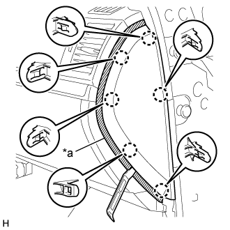
Put protective tape around the instrument side panel RH.
Text in Illustration*a
| Protective Tape
|
Using a moulding remover A, detach the 6 claws and remove the instrument side panel RH.
w/ Airbag Cut Off Switch:
Disconnect the connector and remove the instrument side panel RH.
| 5. REMOVE FRONT DOOR SCUFF PLATE RH |
- HINT:
- Use the same procedures described for the LH side.
| 6. REMOVE COWL SIDE TRIM BOARD RH |
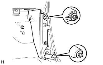
Remove the cap nut.
Text in Illustration*a
| Cap Nut
|
Detach the 2 clips and remove the cowl side trim board LH.
| 7. REMOVE FRONT FLOOR CARPET ASSEMBLY |
Pull back the carpet far enough so that the selector can be removed. For further details, refer to the removal procedure (Click here).
| 8. REMOVE MULTI-DISPLAY CONTROLLER SUB-ASSEMBLY |
Disconnect the connectors and detach the 3 clamps.
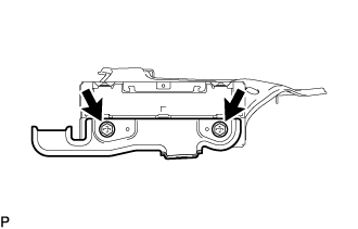
Remove the 3 bolts and multi-display controller sub-assembly.
| 9. REMOVE NO. 2 MULTI-DISPLAY CONTROLLER BRACKET |
Remove the 2 bolts and bracket.
| 10. REMOVE NO. 3 MULTI-DISPLAY CONTROLLER BRACKET |
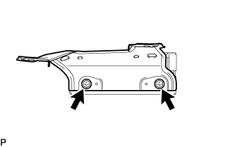
Remove the 2 bolts and bracket.
| 11. REMOVE FRONT CONSOLE BOX |
w/o Cool Box (Click here)w/ Cool Box (Click here)
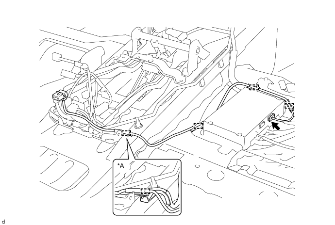
| 12. REMOVE NO. 1 NAVIGATION WIRE |
Detach the clamps.
Text in Illustration*A
| w/ DCM(Telematics Transceiver)
| -
| -
|
Disconnect the connector and remove the No. 1 navigation wire.