Stabilizer Control Valve (W/ Kdss) -- Removal |
| 1. REMOVE STABILIZER CONTROL VALVE PROTECTOR |
Detach the clamp, and disconnect the connector from the protector.
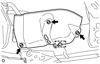 |
Remove the 3 bolts and protector.
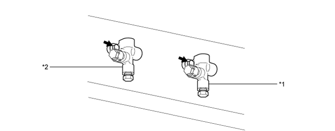
| 2. OPEN STABILIZER CONTROL WITH ACCUMULATOR HOUSING SHUTTER VALVE |
Using a 5 mm hexagon socket wrench, loosen the lower and upper chamber shutter valves of the stabilizer control with accumulator housing 2.0 to 3.5 turns.
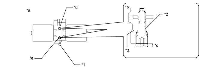
Text in Illustration *1 Bleeder Plug *2 Shutter Valve *3 Block - - *a Bottom view of stabilizer control with accumulator housing *b Side view of stabilizer control with accumulator housing *c 2.0 to 3.5 mm *d Upper Chamber Shutter Valve *e Lower Chamber Shutter Valve - - - NOTICE:
- When loosening a shutter valve, make sure that the end protrudes 2 to 3.5 mm (0.0787 to 0.137 in.) from the surface of the block, and do not turn the shutter valve any further.
- Do not remove the shutter valves.
| 3. REMOVE TAILPIPE ASSEMBLY |
for 1GR-FE:
Remove the tailpipe (Click here).
for 1UR-FE:
Remove the tailpipe (Click here).
for 3UR-FE:
Remove the tailpipe (Click here).
for 1VD-FTV:
Remove the tailpipe (Click here).
| 4. REMOVE CENTER EXHAUST PIPE ASSEMBLY |
for 1GR-FE:
Remove the center exhaust pipe (Click here).
for 1UR-FE:
Remove the center exhaust pipe (Click here).
for 3UR-FE:
Remove the center exhaust pipe (Click here).
for 1VD-FTV:
Remove the center exhaust pipe (Click here).
| 5. DISCHARGE SUSPENSION FLUID PRESSURE |
 |
Connect the hose to the bleeder plug for the stabilizer control with accumulator housing and loosen the bleeder plug.
- CAUTION:
- Be careful as the vehicle height will rapidly decrease when the bleeder plug of the stabilizer control with accumulator housing is loosened.
Discharge the suspension fluid from the stabilizer control with accumulator housing.
After the fluid pressure has dropped and oil has drained out, tighten the bleeder plug and remove the hose.
- Torque:
- 8.3 N*m{85 kgf*cm, 73 in.*lbf}
| 6. REMOVE NO. 2 FRONT STABILIZER CONTROL TUBE ASSEMBLY |
Using a union nut wrench, disconnect the front No. 2 stabilizer control tube from the front No. 1 stabilizer control tube and 2 control adapters.
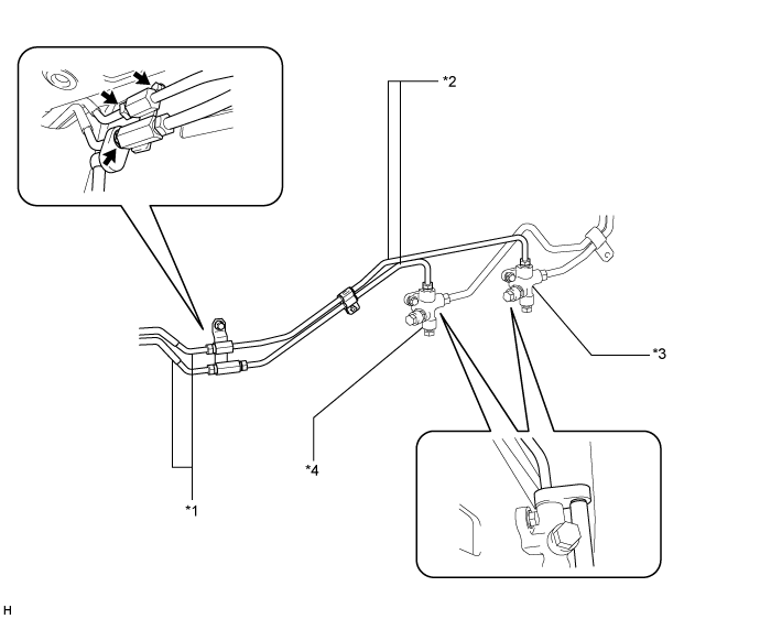
Text in Illustration *1 Front No. 1 Stabilizer Control Tube *2 Front No. 2 Stabilizer Control Tube *3 Stabilizer Control Adapter for Upper Chamber Side *4 Stabilizer Control Adapter for Lower Chamber Side
Remove the bolt and front No. 2 stabilizer control tube from the vehicle.
| 7. REMOVE NO. 1 REAR STABILIZER CONTROL TUBE ASSEMBLY |
Using a union nut wrench, disconnect the rear No. 1 stabilizer control tube from the 2 control adapters and stabilizer control with accumulator housing.
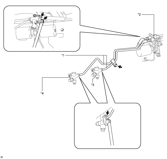
Text in Illustration *1 Rear No. 1 Stabilizer Control Tube *2 Stabilizer Control with Accumulator Housing Assembly *3 Stabilizer Control Adapter for Upper Chamber Side *4 Stabilizer Control Adapter for Lower Chamber Side
Remove the bolt and rear No. 1 stabilizer control tube from the vehicle.
| 8. DISCONNECT NO. 2 REAR STABILIZER CONTROL TUBE ASSEMBLY |
 |
Using a union nut wrench, disconnect the rear No. 2 stabilizer control tube from the stabilizer control with accumulator housing.
| 9. REMOVE STABILIZER CONTROL WITH ACCUMULATOR HOUSING ASSEMBLY |
Remove the cap and bleeder plug from the accumulator housing.
Remove the 2 bolts and stabilizer control with accumulator housing.
 |
| 10. REMOVE STABILIZER CONTROL ADAPTER SUB-ASSEMBLY |
Remove the 2 bolts and 2 stabilizer control adapters from the vehicle.
Text in Illustration *1 Stabilizer Control Adapter for Upper Chamber Side *2 Stabilizer Control Adapter for Lower Chamber Side