Radio Receiver (W/ Multi-Display) -- Installation |
| 1. INSTALL NO. 2 RADIO BRACKET |
Install the No. 2 radio bracket with the 3 screws.
- Torque:
- 3.0 N*m{31 kgf*cm, 27 in.*lbf}
| 2. INSTALL NO. 1 RADIO BRACKET |
Install the No. 1 radio bracket with the 3 screws.
- Torque:
- 3.0 N*m{31 kgf*cm, 27 in.*lbf}
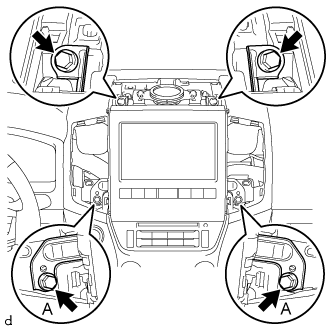
| 3. INSTALL MULTI-MEDIA MODULE RECEIVER ASSEMBLY WITH BRACKET |
Connect the connectors.
Insert the multi-media module receiver assembly to attach the 5 claws on its backside.
- NOTICE:
- When inserting the multi-media module receiver assembly, do not press the knobs on it.
Install the multi-media module receiver assembly with the 2 screws and 2 bolts.
- Torque:
- Bolt A:
- 8.5 N*m{87 kgf*cm, 75 ft.*lbf}
 |
| 4. INSTALL MULTI-DISPLAY ASSEMBLY WITH BRACKET |
Connect the connectors.
Insert the multi-display assembly and attach the 3 clips and 4 claws on its backside.
- NOTICE:
- When inserting the multi-display assembly, do not press the knobs on it.
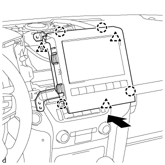 |
Install the multi-display assembly with the 2 screws and 2 bolts.
- Torque:
- Bolt A:
- 8.5 N*m{87 kgf*cm, 75 in.*lbf}
 |
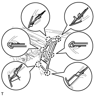
| 5. INSTALL NO. 4 INSTRUMENT PANEL REGISTER ASSEMBLY |
for Type A:
Attach the guide and 7 claws to install the No. 4 instrument panel register assembly.
for Type B:
Attach the 6 claws to install the No. 4 instrument panel register assembly.
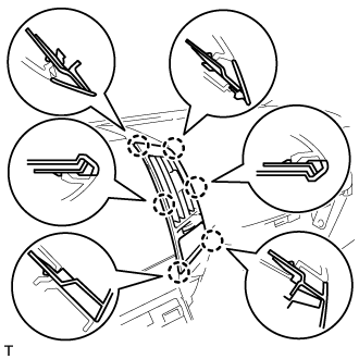
| 6. INSTALL NO. 3 INSTRUMENT PANEL REGISTER ASSEMBLY |
for Type A:
Attach the guide and 7 claws to install the No. 3 instrument panel register assembly.
for Type B:
Attach the 6 claws to install the No. 3 instrument panel register assembly.
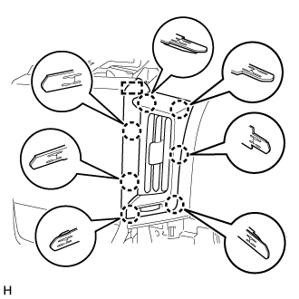
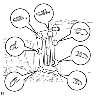
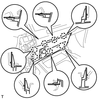
| 7. INSTALL NO. 1 SPEAKER OPENING COVER ASSEMBLY |
 |
Attach the 8 clips to install the No. 1 speaker opening cover assembly.
| 8. INSTALL LOWER CENTER INSTRUMENT CLUSTER FINISH PANEL SUB-ASSEMBLY |
for Type A:
Attach the 6 claws to install the lower center instrument cluster finish panel sub-assembly.
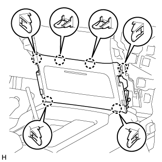
for Type B:
Connect the connectors.
Attach the 7 claws to install the lower center instrument cluster finish panel sub-assembly.
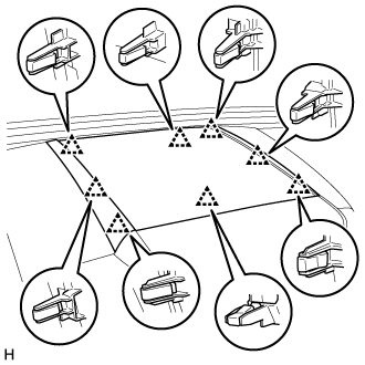
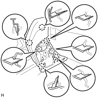
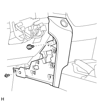
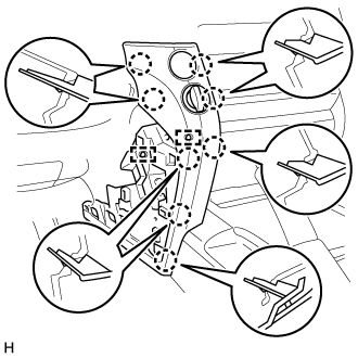
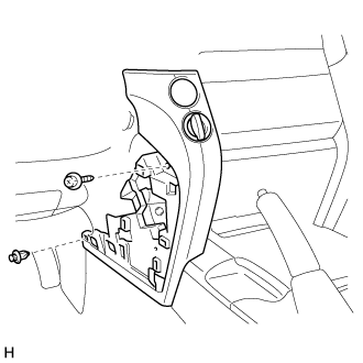
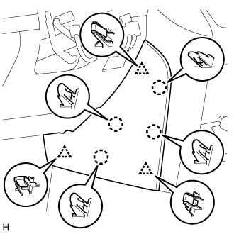
| 9. INSTALL LOWER INSTRUMENT PANEL PAD SUB-ASSEMBLY RH |
for Type A:
Attach the 11 claws and guide to install the lower instrument panel pad sub-assembly RH.
Install the screw and clip.
for Type B:
Attach the 7 claws to install the lower instrument panel pad sub-assembly RH.
Install the screw and clip.
| 10. INSTALL NO. 1 INSTRUMENT PANEL FINISH PANEL CUSHION |
for Type A:
Attach the 4 claws and 3 clips to install the No. 1 instrument panel finish panel cushion.

for Type B:
Attach the 7 claws to install the panel No. 1 instrument panel finish panel cushion.

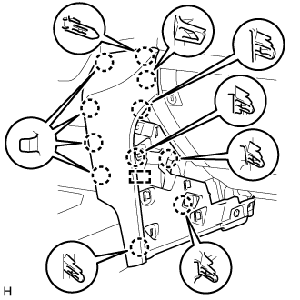
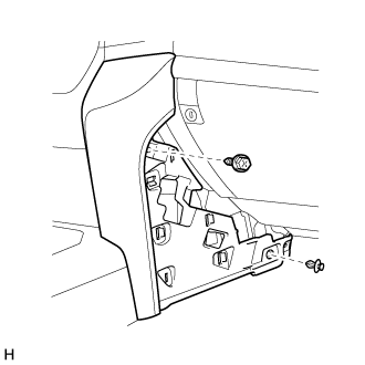
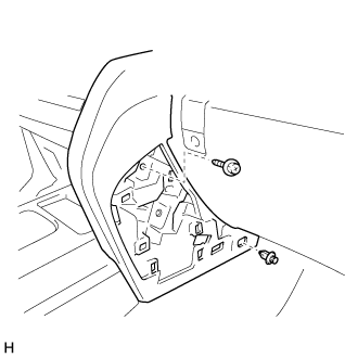
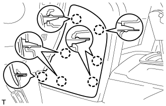
| 11. INSTALL LOWER INSTRUMENT PANEL PAD SUB-ASSEMBLY LH |
for Type A:
Connect the connectors and clamps.
Attach the 11 claws and guide to install the lower instrument panel pad sub-assembly LH.
Install the screw and clip.
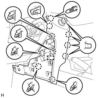
for Type B:
Connect the connectors and clamps.
Attach the 8 claws and 2 guides to install the lower instrument panel pad sub-assembly LH.
Install the screw and clip.
| 12. INSTALL NO. 2 INSTRUMENT PANEL FINISH PANEL CUSHION |
for Type A:
Attach the 4 claws and 3 clips to install the No. 2 instrument panel finish panel cushion.
for Type B:
Attach the 7 claws to install the No. 2 instrument panel finish panel cushion.
| 13. CONNECT CABLE TO NEGATIVE BATTERY TERMINAL |
- NOTICE:
- When disconnecting the cable, some systems need to be initialized after the cable is reconnected (Click here).