Outer Rear View Mirror -- Disassembly |
- HINT:
- Use the same procedure for RHD and LHD vehicles.
- The procedure listed below is for LHD vehicles.
- Use the same procedure for the RH and LH sides.
- The procedure listed below is for the LH side.
| 1. REMOVE OUTER MIRROR LH |
Push the upper part of the mirror surface and tilt it.
 |
Using a moulding remover, detach the 4 claws and separate the outer mirror LH from the mirror body.
- HINT:
- Apply protective tape to the outer rear mirror LH to prevent it from being damaged.
w/ Blind Monitor System:
Disconnect the connector and remove the outer mirror LH.
 |
w/ EC Mirror:
Disconnect the connector and remove the outer mirror LH.
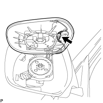 |
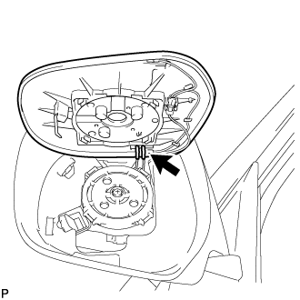
w/ Mirror Heater:
Disconnect the 2 connectors and remove the outer mirror LH.
 |
| 2. REMOVE OUTER MIRROR COVER LH |
 |
- HINT:
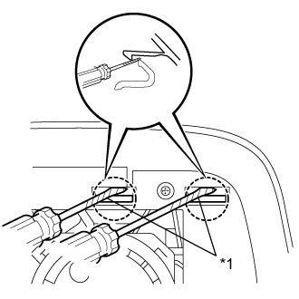
- Be sure to detach the claws of the outer mirror cover in the order shown in the illustration.
Using 2 screwdrivers, detach the 2 claws.
- HINT:
- Tape the screwdriver tip before use.
Text in Illustration *1 Protective Tape
 |
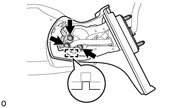
Insert a screwdriver into the slot as shown in the illustration and push on the outer mirror body to create a space between the outer mirror body and outer mirror cover.
- NOTICE:
- Be careful not to break the ribs.
- HINT:
- Tape the screwdriver tip before use.
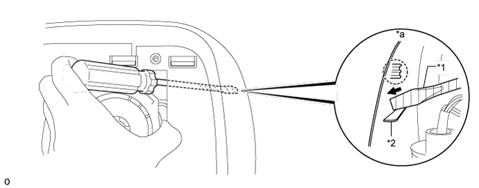
Text in Illustration *1 Protective Tape *2 Rib *a Inner Side of Outer Mirror Cover - -
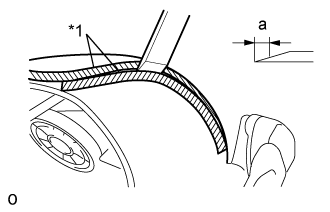
Insert a moulding remover into the space made between the outer mirror body and outer mirror cover.
- NOTICE:
- Do not insert the moulding remover more than 4 mm (0.157 in.).
- HINT:
- Tape the moulding remover before use.
- Standard:
Area Specified Condition a 4mm
Text in Illustration *1 Protective Tape
 |
Slide the moulding remover downwards as shown in the illustration to detach the 2 claws.
- NOTICE:
- Do not insert the moulding remover more than 4 mm (0.157 in.).
- Do not slide the moulding remover past the point approximately 40 mm (1.57 in.) from the bottom edge of the outer mirror cover as the outer mirror body will become damaged.
- Standard:
Area Specified Condition a 40mm b 4mm
Text in Illustration *1 Protective Tape
 |
Remove the moulding remover B.
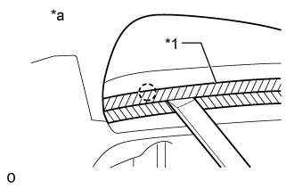
Apply protective tape to the areas of the body cover and outer mirror cover as shown in the illustration.
Text in Illustration *1 Protective Tape *a Lower Side
 |
Insert a moulding remover B between the outer mirror cover and outer mirror body as shown in the illustration and detach the claw.
Using a screwdriver, detach the claw.
Text in Illustration *1 Protective Tape
 |
Detach the 2 claws and remove the outer mirror cover.
- NOTICE:
- When removing the cover, be careful not to damage the side turn signal light assembly or cover.
 |
| 3. REMOVE SIDE TURN SIGNAL LIGHT ASSEMBLY LH |
Remove the 3 screws and light.
 |
Disconnect the connector.
| 4. REMOVE OUTER MIRROR RETRACTOR LH (w/ Multi-terrain Monitor) |
Remove the gasket
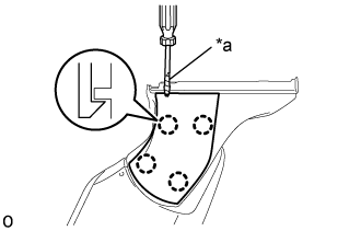
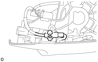
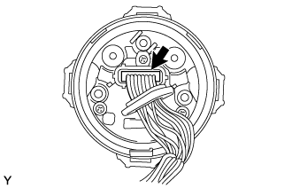
Cut the wire harness at the position shown in the illustration.
Text in Illustration *a Cut the wire harness here Remove the tape.
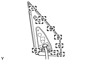
Detach the 9 guides and remove the gasket.
- NOTICE:
- Make sure to replace the gasket with a new one.

Remove the lower mirror cover
Using a tin-blade screwdriver, detach the 4 claws and remove the lower mirror cover.
- HINT:
- Tape the tin-blade screwdriver tip before use.
Text in Illustration *a Protective Tape - NOTICE:
- Make sure to replace the mirror cover lower with a new one.
Remove the base
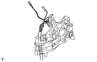
Remove the wire harness.
Using "TORX" socket wrench T25, remove the 3 "TORX" screws.
- NOTICE:
- Make sure to replace the "TORX" screws with new ones.
Detach the guide and remove the base.
Remove the body
Remove the 5 screws and body.
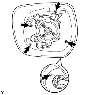
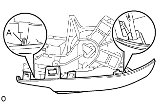
Remove the body cover
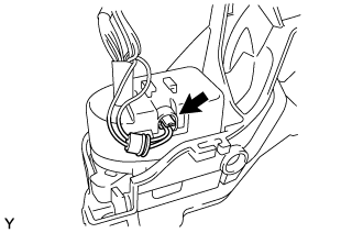
Detach the 2 claws and remove the connector from body cover.
Disconnect the connector.
Detach the 2 guides and remove the body cover.
- NOTICE:
- Be careful not to break the guide shown in the part of the illustration labeled A.
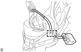
Remove the actuator sub-assembly
Remove the 3 screws.
Detach the 2 clamps and open the cover.
Disconnect the connector and remove the actuator sub-assembly.


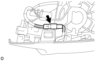
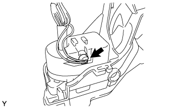
Remove the wire harness
Detach the clamp.
Open the cover.
Disconnect the connector.
Remove the wire harness.
Remove the support spring
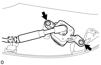
Remove the 2 screws.
Detach the 6 claws and remove the 2 support springs.

| 5. REMOVE SIDE TELEVISION CAMERA ASSEMBLY (w/ Multi-terrain Monitor) |
Detach the clamp.
 |
Remove the 2 screws and side television camera assembly LH.