CLOSE STABILIZER CONTROL WITH ACCUMULATOR HOUSING SHUTTER VALVE
PERFORM VARIABLE GEAR RATIO STEERING SYSTEM CALIBRATION (w/ VGRS)
Steering Linkage -- Installation |
- HINT:
- Use the same procedure for RHD and LHD vehicles.
- The procedure listed below is for LHD vehicles.
| 1. INSTALL POWER STEERING LINK ASSEMBLY |
Install the power steering link with the 3 bolts and 3 nuts.
- Torque:
- 120 N*m{1224 kgf*cm, 89 ft.*lbf}
- HINT:
- Hold the bolts and tighten the nuts to install the power steering link.
| 2. INSTALL FRONT SUSPENSION REBOUND STOPPER SUB-ASSEMBLY LH |
Install the suspension rebound stopper LH with the 3 bolts.
- Torque:
- 58 N*m{591 kgf*cm, 43 ft.*lbf}
 |
| 3. INSTALL FRONT SUSPENSION REBOUND STOPPER SUB-ASSEMBLY RH |
Install the suspension rebound stopper RH with the 3 bolts.
- Torque:
- 58 N*m{591 kgf*cm, 43 ft.*lbf}
 |
| 4. CONNECT PRESSURE FEED TUBE ASSEMBLY |
Install the pressure feed tube clamp with the 2 bolts.
- Torque:
- 18 N*m{184 kgf*cm, 13 in.*lbf}
Connect the pressure feed tube (return tube side) to the power steering link with the clamp.
Using a union nut wrench, connect the pressure feed tube (pressure feed tube side) to the power steering link.
- Torque:
- 44 N*m{449 kgf*cm, 32 ft.*lbf}
- NOTICE:
- Use the formula to calculate special torque values for situations where a union nut wrench is combined with a torque wrench (Click here).
 |
| 5. INSTALL TIE ROD END SUB-ASSEMBLY LH |
Align the matchmarks of the tie rod and rack end, and temporarily install the tie rod with the lock nut.
- HINT:
- After adjusting toe-in, tighten the lock nut.
- Torque:
- 82 N*m{836 kgf*cm, 60 ft.*lbf}
Check that length A is the same as the length measured previously.
| 6. INSTALL TIE ROD END SUB-ASSEMBLY RH |
- HINT:
- Use the same procedures described for the RH side.
| 7. INSTALL STEERING RACK BOOT PROTECTOR LH |
Install the steering rack boots protector with the 2 bolts.
- Torque:
- 29 N*m{296 kgf*cm, 21 ft.*lbf}
| 8. INSTALL STEERING RACK BOOT PROTECTOR RH |
- HINT:
- Use the same procedures described for the RH side.
| 9. CONNECT TIE ROD END SUB-ASSEMBLY LH |
Connect the tie rod end LH to the steering knuckle with a new nut.
- Torque:
- 69 N*m{704 kgf*cm, 51 ft.*lbf}
Install a new cotter pin.
- HINT:
- If the holes for the cotter pin are not aligned, tighten the nut up to another 60°.
| 10. CONNECT TIE ROD END SUB-ASSEMBLY RH |
- HINT:
- Use the same procedures described for the LH side.
| 11. CONNECT NO. 2 STEERING INTERMEDIATE SHAFT |
for Manual Tilt and Telescopic:
Connect the No. 2 steering intermediate shaft (Click here).
for Power Tilt and Power Telescopic:
Connect the No. 2 steering intermediate shaft (Click here).
| 12. TEMPORARILY INSTALL FRONT STABILIZER BAR |
w/ KDSS:
Temporarily install the stabilizer bar (Click here).
w/o KDSS:
Temporarily install the stabilizer bar (Click here).
| 13. TEMPORARILY INSTALL FRONT STABILIZER LINK ASSEMBLY LH |
w/ KDSS:
Temporarily install the stabilizer link (Click here).
w/o KDSS:
Temporarily install the stabilizer link (Click here).
| 14. TEMPORARILY INSTALL FRONT STABILIZER LINK ASSEMBLY RH |
- HINT:
- Use the same procedures described for the LH side.
| 15. INSTALL ENGINE ASSEMBLY |
for 1UR-FE:
Install the engine (Click here).
for 1GR-FE:
Install the engine (Click here).
for 1VD-FTV:
Install the engine (Click here).
for 3UR-FE:
Install the engine (Click here).
| 16. TIGHTEN FRONT NO. 1 STABILIZER BRACKET LH |
w/ KDSS:
Tighten the stabilizer bracket (Click here).
w/o KDSS:
Tighten the stabilizer bracket (Click here).
| 17. TIGHTEN FRONT NO. 1 STABILIZER BRACKET RH |
- HINT:
- Use the same procedures described for the LH side.
| 18. STABILIZE SUSPENSION |
Install the front wheels.
- Torque:
- for aluminum wheel:
- 131 N*m{1336 kgf*cm, 97 ft.*lbf}
- for steel wheel:
- 209 N*m{2131 kgf*cm, 154 ft.*lbf}
Lower the vehicle.
Press down on the vehicle several times to stabilize the suspension.
| 19. TIGHTEN FRONT STABILIZER LINK ASSEMBLY LH |
w/ KDSS:
Tighten the stabilizer link (Click here).
w/o KDSS:
Tighten the stabilizer link (Click here).
| 20. TIGHTEN FRONT STABILIZER LINK ASSEMBLY RH |
- HINT:
- Use the same procedures described for the LH side.
| 21. TIGHTEN FRONT STABILIZER BAR |
w/ KDSS:
Tighten the front stabilizer bar (Click here).
w/o KDSS:
Tighten the front stabilizer bar (Click here).
| 22. BLEED POWER STEERING FLUID |
for 1UR-FE:
Bleed the power steering fluid (Click here).
for 1GR-FE:
Bleed the power steering fluid (Click here).
for 1VD-FTV:
Bleed the power steering fluid (Click here).
for 3UR-FE:
Bleed the power steering fluid (Click here).
| 23. CHECK POWER STEERING FLUID LEVEL |
| 24. CHECK FOR POWER STEERING FLUID LEAK |
| 25. INSTALL FRONT WHEELS |
| 26. PLACE FRONT WHEELS FACING STRAIGHT AHEAD |
- HINT:
- Perform this procedure with the front of the vehicle jacked up.
| 27. ADJUST FRONT WHEEL ALIGNMENT |
Adjust the front wheel alignment (Click here).
| 28. ADJUST HEADLIGHT ASSEMBLY |
for Halogen Headlight:
Adjust the headlight (Click here).
for LED Headlight:
Adjust the headlight (Click here).
for Halogen and LED Headlight:
Adjust the headlight (Click here).
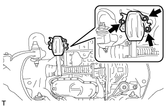
| 29. CLOSE STABILIZER CONTROL WITH ACCUMULATOR HOUSING SHUTTER VALVE |
- NOTICE:
- Perform the inspection on a level surface.
- Ensure that the wheels are on the ground and facing straight ahead.
- Perform the inspection with the vehicle load completely on the suspension.
- HINT:
- Perform this step with the fuel tank full.
- If there are any parts installed to the vehicle which place any unbalanced load on the left or right side of the vehicle, remove them.
Using a 5 mm hexagon socket wrench, tighten the lower and upper chamber shutter valves of the stabilizer control with accumulator housing.
- Torque:
- 14 N*m{140 kgf*cm, 10 ft.*lbf}
| 30. PERFORM VARIABLE GEAR RATIO STEERING SYSTEM CALIBRATION (w/ VGRS) |